KE2040 Instruction Manual_ver1.30.pdf - 第790页
13 − 8 13.5.1 Installing the Matrix Tray Changer (MTC) 13.5.1.1 T R-4SN instal l start posi tion Figure 13.5.1. 1 Appearance of TR-4SN to be i nstalled CA UTION To avoid any accident caused by sudden activat ion of the m…
13 − 7
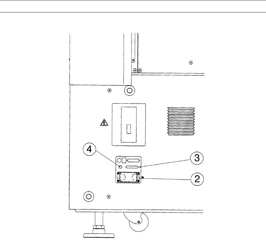
4) Connect the MTC power plug ② and signal connector ③ to the corresponding
jack/connector and the air tube to the MTC air fitting of the interface panel located
on the right side of the main unit.
Note: Be sure to use the cable and air tube supplied with the MTC.
Figure 13.5.3
② MTC power jack
③ MTC interface connector
④ MTC
ソ
6 tube inlet
13 − 8
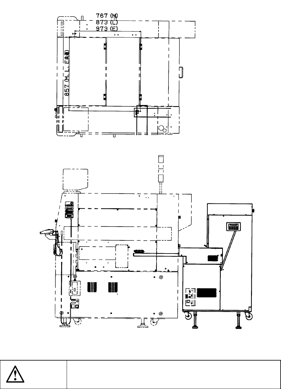
13.5.1 Installing the Matrix Tray Changer (MTC)
13.5.1.1 TR-4SN install start position
Figure 13.5.1.1 Appearance of TR-4SN to be installed
CAUTION
To avoid any accident caused by sudden activation of the machine,
turn off the power.
13 − 9
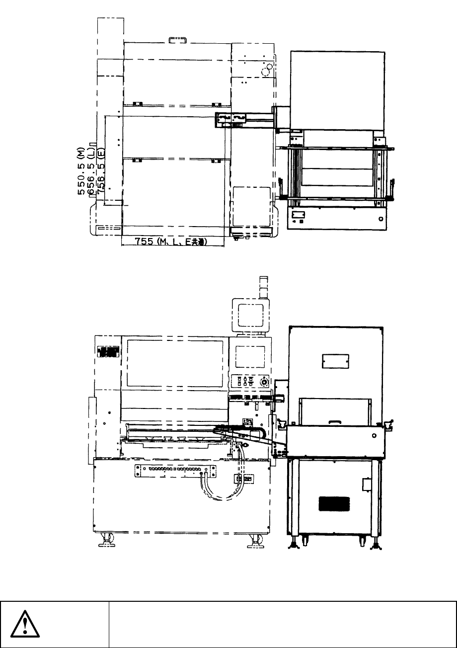
13.5.1.2 TR-6SN/TR-6DN install start position
Figure 13.5.1.2 Appearance of TR-6SN/TR-6DN to be installed
CAUTION
To avoid any accident caused by sudden activation of the machine,
turn off the power.