KE2040 Instruction Manual_ver1.30.pdf - 第800页
13 − 18 13.11 Handling a Gripper Nozzle This nozzle is designed exclusively f or the KE- 2000 series of pr oducts to pick up and/or place on a board a com ponent whose top has no picked-up ar ea, and it is available to l…
13 − 17
4. Operation
(1) Teaching
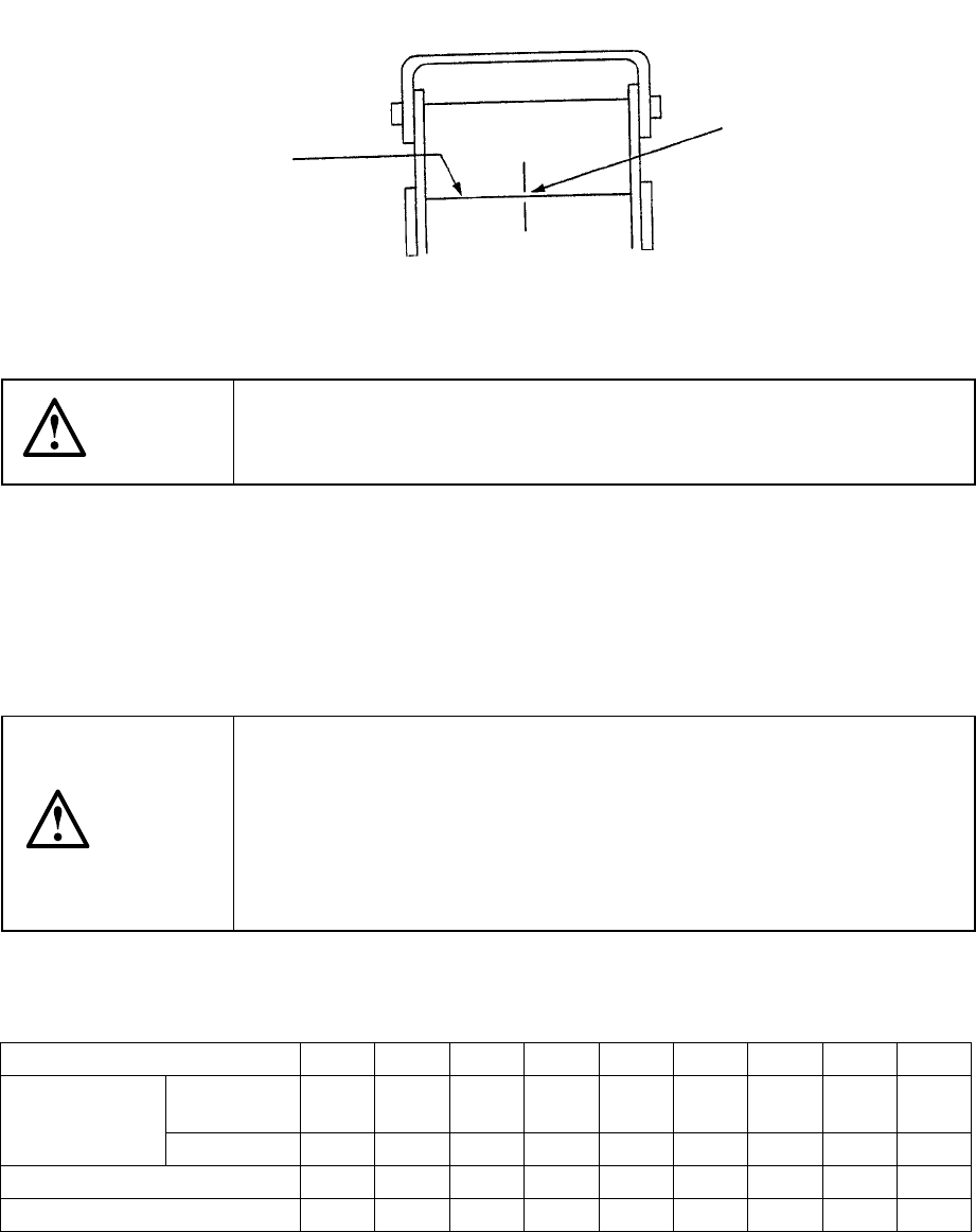
Fix the IC collection belt on the feeder bank, and teach the coordinates of the IC
collection belt position which is selected on the Machine setup menu.
Teaching position
Figure 13.10.3 Teaching operation
CAUTION
To avoid a risk of injury, do not place your hand in the machine, nor
move your face or head close to the machine during operation of the
HOD.
(2) Basic operation
The head of the main unit places an IC on the belt, and the component sensor
detects it. After 0.5 seconds, the IC is fed over the belt at the pitch you set. If
the belt gets full of ICs and stops, press the Reset switch to restart the machine
after removing ICs from the belt.
CAUTION
To avoid a risk of injury and prevent the machine from being damaged,
be sure to collect components only after detaching the IC collection belt
from the feeder bank or after you check to see if the machine stops
completely.
If you are to collect components from the IC collection belt being fixed
on the feeder bank, be sure to check to see if there is no person who
may start the machine unexpectedly.
Table 13.10.1 Number of ICs which can be collected
and the feeding pitch set with the rotary switch No.
Switch No. to be set 1 2 3 4 5 6 7 8 9
Equal or
less than
10 15 20 25 30 35 40 45 50 IC size (mm)
Over − 10 15 20 25 30 35 40 45
Belt feeding pitch (mm) 15 20 25 30 35 40 45 50 55
Maximum number of ICs 19 14 11 9 8 7 6 6 5
Optical axis
Teach the center of the
belt on the component
sensor optical axis.
13 − 18
13.11 Handling a Gripper Nozzle
This nozzle is designed exclusively for the KE-2000 series of products to pick up
and/or place on a board a component whose top has no picked-up area, and it is
available to laser and vision recognition.
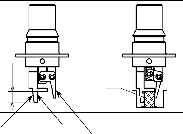
1. Features
The gripper nozzle uses its “fixed arm” and “swing arm” together exclusively to
pick up and/or place a component whose topside has no picked-up area. Its grip
strength is appropriate enough to pick up/place a component stably.
① Fixed arm
② Swing arm
Figure 13.11.1 Name of each part of a nozzle
①
①①
①
②
②②
②
Com
p
onent
Position against a
component is pushed
Length of a lug
13 − 19
2. Specifications
(1) Required components and software
◇
A floppy disk on which a nozzle information file is stored is supplied with a
nozzle. This disk is required to use a gripper nozzle.
◇ The software version of the main unit that supports control over a gripper
nozzle is 1.11 or higher.
◇ The dimensions of a gripper nozzle arm should match a shape and size of
each component and a shape of a feeder such as a tape and tray.
[See “(5) Applicable components and packaging style”.]
(2) Method
Centering method: Laser and vision
(3) Component placement precision
Component placement precision : ± 0.3 mm or less (3 σ)
Note that the attained precision may vary depending on the shape of a
component.
When the system places a component whose portion to be aligned with laser
has an edge, whose molded part has a burr, or whose portion to be inspected
with the system cannot be fixed to a pick-up device, the precision described
above cannot be attained.
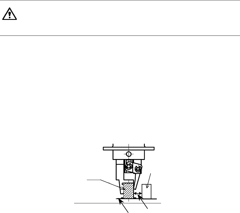
(4) Limited adjacent components
When the system places a component, a gripper swing arm opens, so it may
be in contact with an adjacent component.
Therefore, there are the following two restraints on operations of a gripper
nozzle:
◇ The height of a component to be placed with a gripper nozzle should be 3
mm or more higher than that of adjacent components.
◇ The side of a component to be held with the swing arm of the gripper
nozzle should be far from adjacent components by 4 mm or more.
(See the figure below.)
Component B
Component A
Board Note: Components A and B
should another by at
least 4mm.