YSI_Prog_E.pdf - 第127页
3-4 3 Step screen 1.3 Detection conditions parameters Sets the inspection conditions for the object to be inspected in the area recognized in red as the inspection object. TIP The displayed parameters differ depending on…

3-3
3
Step screen
3. Settings list (luminance, compatible)
Sets the Sampling Light, Reduced Light, Noise Cut, and Reduced Light Ratio.
4. Multiple threshold value settings (luminance, compatible)
This is used if there is a difference in luminance in the object being inspected. Up to four threshold values can be set for
a single step.
5. [Sampling Light] button (color, shape)
This is used to set the sampling light for inspection. By pressing this button, a sampling light selection dialog box
appears. Select the image in which the contrast of the object being inspected is clearest, and then press the [OK] button.
The selected sampling light is set in the "Sampling Light" field.
6. Noise cut (color, shape, X-ray)
Selects the size for cutting the influence of noise.
7, 8. Threshold slide bars
Adjust the threshold by dragging with the mouse.
9. Light Type
Select the light type from the drop-down lists.
10.
[Light List] button
Select the image for inspection from the displayed "Light List".
11
. [Insp. Img] button
By pressing this button, an inspection image screen appears.
12
. Slant Thresh
After checking, enter the standard size and adjust the threshold with the slide bar.
13
. Relative Thresh
After checking, enter the standard size and adjust the threshold with the slide bar.
14
. Sampling Mode
Select whether to specify faults with one point or with a range from drop-down list.
15
. Sampling Height slide bar (mm)
Adjust the sampling height by dragging with the mouse.
16
. Sampling Thickness slide bar (mm)
Adjust the sampling thickness by dragging with the mouse.
3-4
3
Step screen
1.3 Detection conditions parameters
Sets the inspection conditions for the object to be inspected in the area recognized in red as the inspection
object.
TIP
The displayed parameters differ depending on the inspection status. For details on parameter settings for each status,
see Chapter 4, "Inspection status", in this manual.
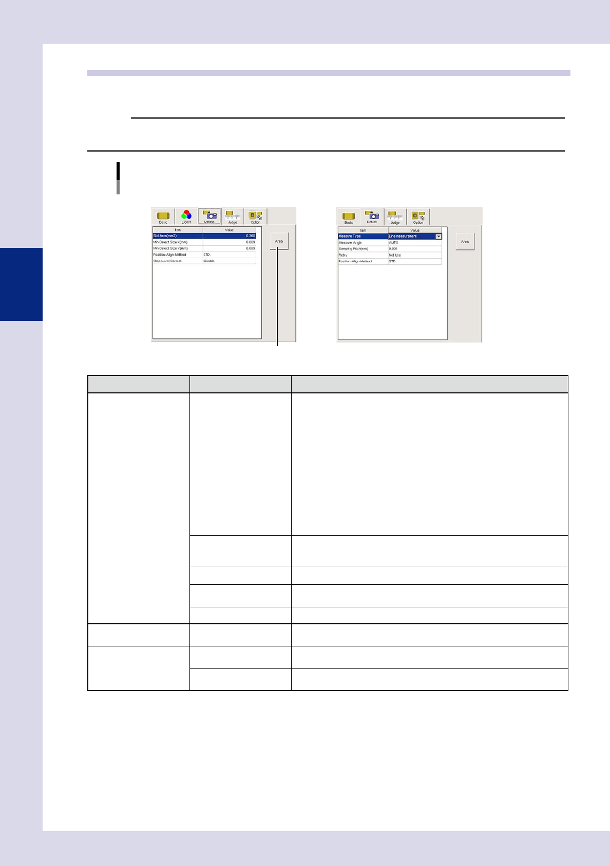
Detection conditions parameters
Inspection status "Solder Quantity Check", "Height Measure" example
N Solder Quantity Check N Height Measure
[Area] button
24303-P6-00
Inspection status Item Details
Common Position-Align-Method
• STD.
If the "Position-Align-Method" in basic parameters for the parts check and
electrode check for that part is set to "Enable", alignment is performed
with that position alignment method.
• Invalid
Even if the "Position-Align-Method" in basic parameters for the parts check
and electrode check for that part is set to "Enable", alignment is not
performed with that position alignment method.
• Change-step-size
If the "Position-Align-Method" in basic parameters for the parts check and
electrode check for that part is set to "Enable", alignment is performed
with that position alignment method, however, alignment is not performed
in the basic parameters "Lead Group" setting direction.
• Mask Correct
Aligns only the mask position set in the options.
Std Area (mm
2
)
This is the area of the selected step.
By pressing the [Area] button, the step area is entered. If the step size is
changed, the changed area is automatically entered.
Min Detect Size X, Y (mm) Sets the minimum X and Y size for the area to be inspected.
Min Area (%)
Sets the minimum area for the area to be inspected. Enter a percentage of
the standard area.
Step Level Correct Offsets with the difference in luminance level step for the same parts.
Foreign object check only Foreign Object Level
This is the luminance difference level for inspection objects detected as
foreign objects. Enter 0 to 255.
Character check only Character Size X (mm)
Enter the X size for characters being inspected. Enter "AUTO" if the size is
not known.
Character Size Y (mm)
Enter the Y size for characters being inspected. Enter "AUTO" if the size is
not known.
3-5
3
Step screen
Inspection status Item Details
Height measurement only
Measure Type
Select the height measurement type from "STD.", "Point measurement", or
"Line measurement".
• STD.
Sets the height for this step as the standard step.
• Point measurement
Measures the height of the inspection object at points.
• Line measurement
Measures the height of the inspection object while moving at the
movement pitch, and sets the maximum value as the parts height.
Measure Angle
Sets the laser reflection angle. If "AUTO" is set, laser is reflected on the part
exterior.
Measure Method
This is displayed only if "STD." is selected for the Measure Type.
Selects the method used to obtain the measurement result.
Sampling Pitch
This is displayed only if "Line measurement" is selected for the Measure
Type.
Selects the pitch at which measurement is performed while the laser height
sensor moves.
Retry
This is displayed only if "Point measurement" or "Line measurement" is
selected for the Measure Type. If "Use" is selected at line measurement,
inspection is performed with the movement direction reversed.
[Area] button
Pressing the [Area] button sets the step area for the standard area.