YSI_Prog_E.pdf - 第128页
3-5 3 Step screen Inspection status Item Details Height measurement only Measure T ype Select the height measurement type from "STD.", "Point measurement", or "Line measurement". • STD. Sets…
3-4
3
Step screen
1.3 Detection conditions parameters
Sets the inspection conditions for the object to be inspected in the area recognized in red as the inspection
object.
TIP
The displayed parameters differ depending on the inspection status. For details on parameter settings for each status,
see Chapter 4, "Inspection status", in this manual.
Detection conditions parameters
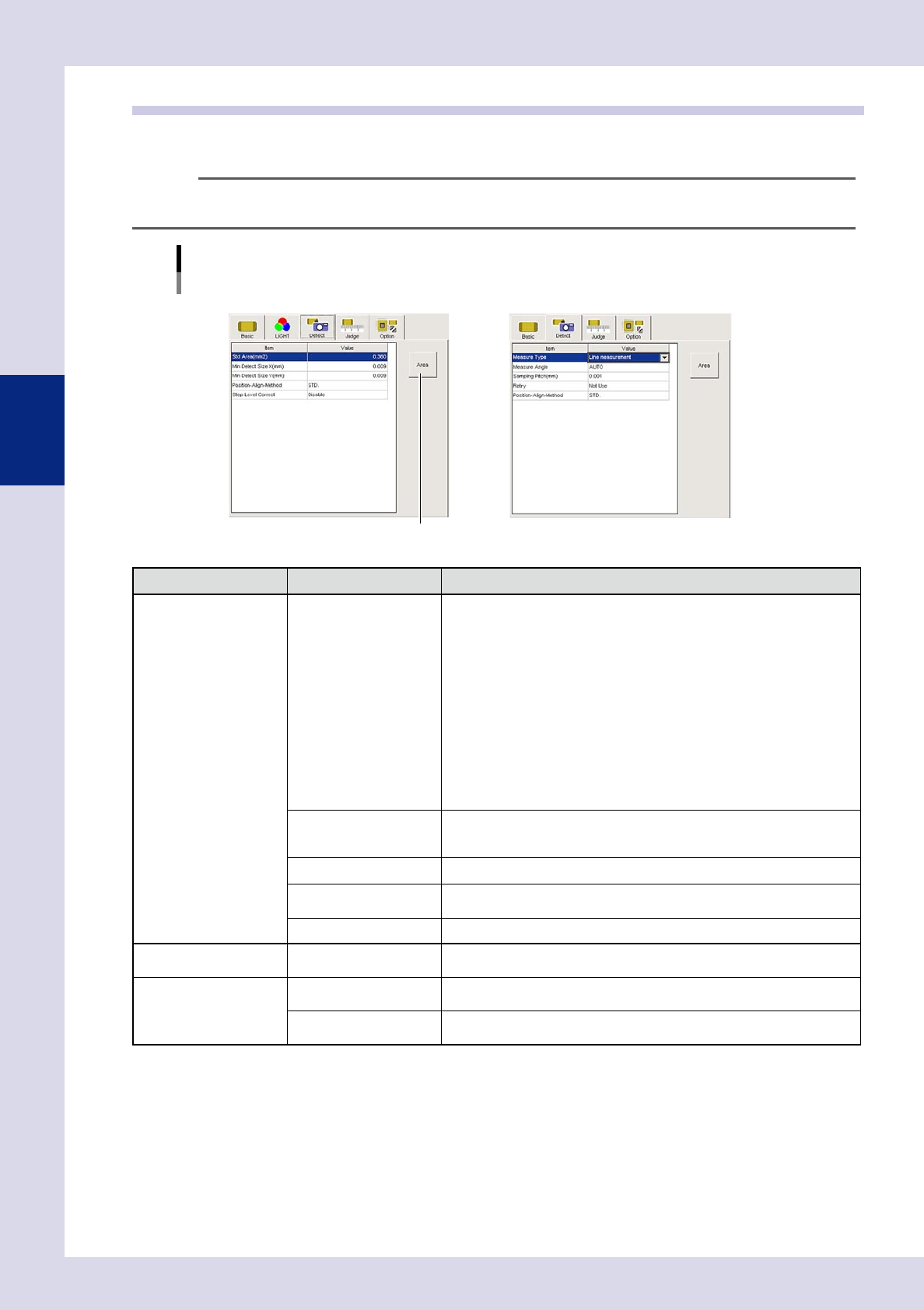
Inspection status "Solder Quantity Check", "Height Measure" example
N Solder Quantity Check N Height Measure
[Area] button
24303-P6-00
Inspection status Item Details
Common Position-Align-Method
• STD.
If the "Position-Align-Method" in basic parameters for the parts check and
electrode check for that part is set to "Enable", alignment is performed
with that position alignment method.
• Invalid
Even if the "Position-Align-Method" in basic parameters for the parts check
and electrode check for that part is set to "Enable", alignment is not
performed with that position alignment method.
• Change-step-size
If the "Position-Align-Method" in basic parameters for the parts check and
electrode check for that part is set to "Enable", alignment is performed
with that position alignment method, however, alignment is not performed
in the basic parameters "Lead Group" setting direction.
• Mask Correct
Aligns only the mask position set in the options.
Std Area (mm
2
)
This is the area of the selected step.
By pressing the [Area] button, the step area is entered. If the step size is
changed, the changed area is automatically entered.
Min Detect Size X, Y (mm) Sets the minimum X and Y size for the area to be inspected.
Min Area (%)
Sets the minimum area for the area to be inspected. Enter a percentage of
the standard area.
Step Level Correct Offsets with the difference in luminance level step for the same parts.
Foreign object check only Foreign Object Level
This is the luminance difference level for inspection objects detected as
foreign objects. Enter 0 to 255.
Character check only Character Size X (mm)
Enter the X size for characters being inspected. Enter "AUTO" if the size is
not known.
Character Size Y (mm)
Enter the Y size for characters being inspected. Enter "AUTO" if the size is
not known.
3-5
3
Step screen
Inspection status Item Details
Height measurement only
Measure Type
Select the height measurement type from "STD.", "Point measurement", or
"Line measurement".
• STD.
Sets the height for this step as the standard step.
• Point measurement
Measures the height of the inspection object at points.
• Line measurement
Measures the height of the inspection object while moving at the
movement pitch, and sets the maximum value as the parts height.
Measure Angle
Sets the laser reflection angle. If "AUTO" is set, laser is reflected on the part
exterior.
Measure Method
This is displayed only if "STD." is selected for the Measure Type.
Selects the method used to obtain the measurement result.
Sampling Pitch
This is displayed only if "Line measurement" is selected for the Measure
Type.
Selects the pitch at which measurement is performed while the laser height
sensor moves.
Retry
This is displayed only if "Point measurement" or "Line measurement" is
selected for the Measure Type. If "Use" is selected at line measurement,
inspection is performed with the movement direction reversed.
[Area] button
Pressing the [Area] button sets the step area for the standard area.
3-6
3
Step screen
1.4 Judgment conditions parameters
Sets parameters used to judge whether the object being inspected is OK or NG.
TIP
The displayed parameters differ depending on the inspection status. For details on parameter settings for each status,
see Chapter 4, "Inspection status", in this manual.
Judgment conditions parameters
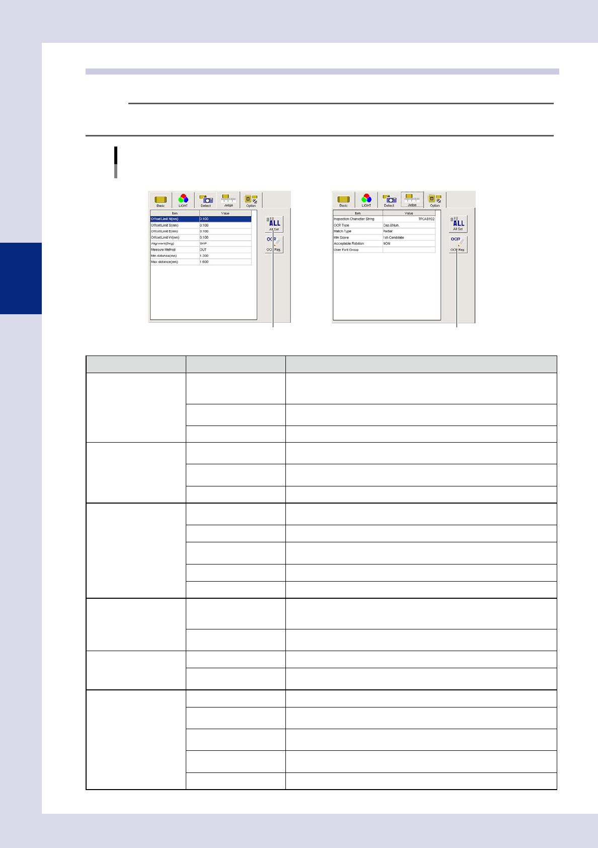
Inspection status "Electrode Check", "Character Recognition" example
NElectrode Check
[All Set] button
NCharacter Recognition
[OCR Reg.] button
24304-P6-00
Inspection status Item Details
Parts Check
Offset Limit N - W (mm)
Sets the allowable amount that the recognized area edge may protrude from
the step frame. The detection area within this allowable amount is subject to
area calculation. Set based on the parts size and pattern design.
Min Area, Max Area (%)
Sets the percentage of the minimum and maximum area with respect to the
standard area.
Alignment (Deg) Enter the maximum tolerance angle for parts
θ
displacement inspection.
Position Align
Align Area Limit N - W
(±mm)
Enter maximum ranges for position alignment. An inspection NG result will
occur if these values are exceeded.
Min Area, Max Area (%)
Sets the percentage of the minimum and maximum area with respect to the
standard area.
Alignment (Deg) Enter the maximum tolerance angle for parts
θ
displacement inspection.
Electrode Check
Offset Limit N - W (mm)
Sets the allowable amount that the recognized area edge may protrude from
the step frame. Set based on the parts size and pattern design.
Alignment (Deg) Enter the maximum tolerance angle for chip parts
θ
displacement inspection.
Measure Method
Specifies whether to measure the electrode inner side distance or the outer
side distance.
Min distance (mm) Sets the OK parts minimum distance.
Max distance (mm) Sets the OK parts maximum distance.
Polarity Check
Offset Limit N - W (mm)
Sets the allowable amount that the recognized area edge may protrude from
the step frame. The detection area within this allowable amount is subject to
area calculation. Set based on the parts size and pattern design.
Min Area, Max Area (%)
Sets the percentage of the minimum and maximum area with respect to the
standard area.
Solder quantity check
Offset Limit N - W (mm) This should normally be set to "0".
Min Area, Max Area (%)
Sets the percentage of the minimum and maximum area with respect to the
standard area.
Lead Check
Offset Limit N - W (mm) This should normally be set to "0".
Max Accept Size X, Y
(mm)
An NG is judged if the recognized area is greater than the set value.
Pin Number Check
An NG is judged if the number of pins on the recognized object differs from
the specified number of pins.
Min Area, Max Area (%)
Sets the minimum and maximum area percentage with respect to the
standard area for the area subject to pin quantity inspection.
Lead Space Check (mm) Sets the minimum value for the distance between leads.