YSI_Prog_E.pdf - 第79页
2-8 2 Inspection data creation and tuning 1.3.2 Inspection with X-ray camera n Solder inspection of lower surface electrode par ts • Ball joint check Inspection is performed with X-ra y horizontal tomographic images obta…
2-7
2
Inspection data creation and tuning
n
Fillet
•
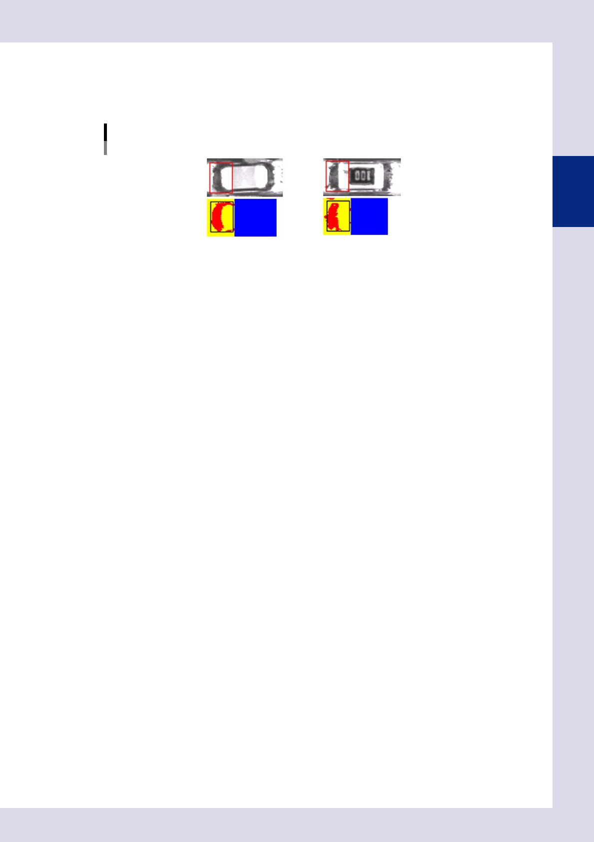
Quantity solder check (solder amount check)
This inspection can be used to detect the fillet area, and determines whether a fillet is formed or not based on that
result.
Quantity solder check (solder amount check)
23211-P6-00
2-8
2
Inspection data creation and tuning
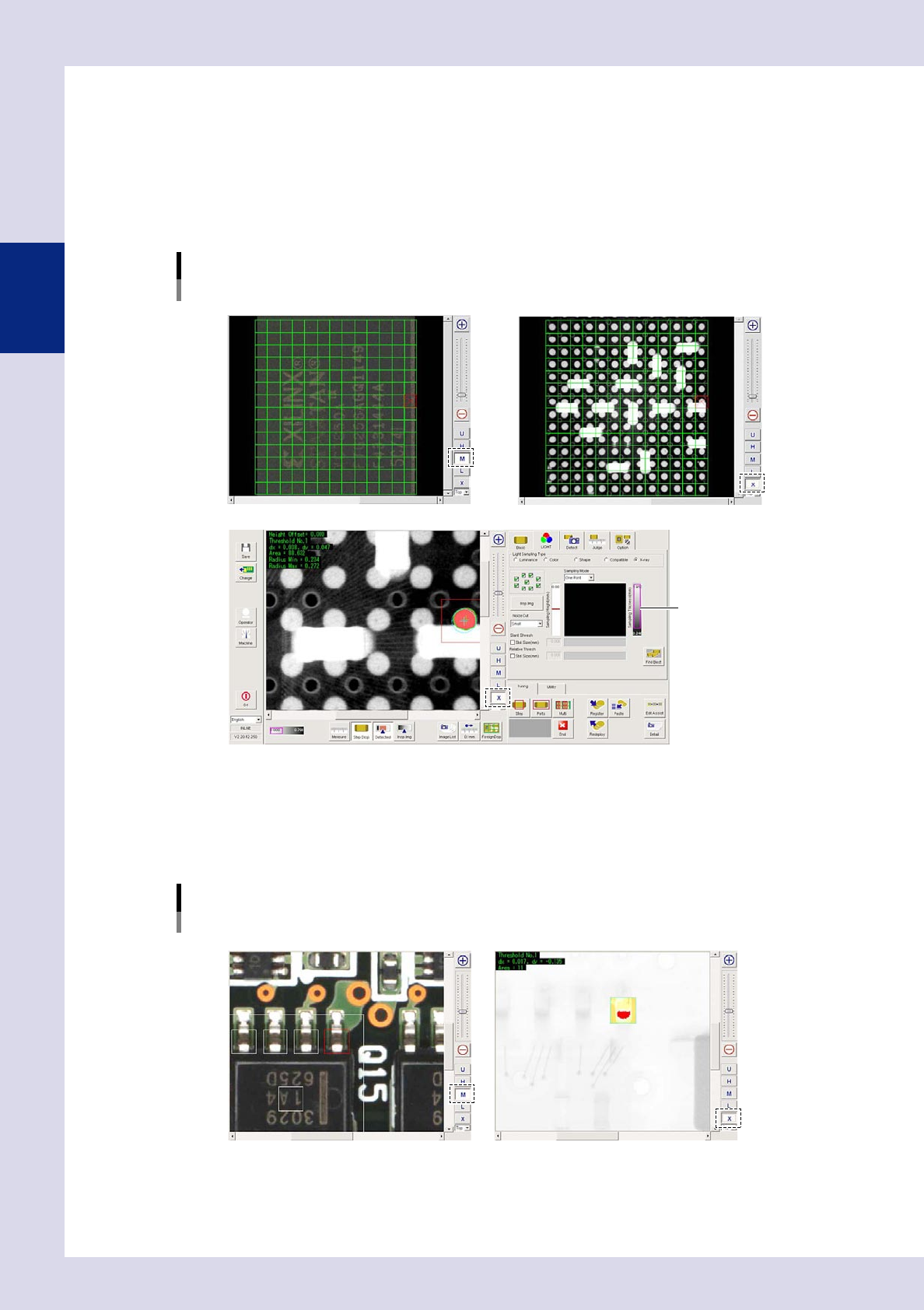
1.3.2 Inspection with X-ray camera
n
Solder inspection of lower surface electrode parts
•
Ball joint check
Inspection is performed with X-ray horizontal tomographic images obtained with digital laminography. Solder is detected
from X-ray horizontal images of joint surfaces on lower surface electrode parts, and judgment is made based on the
detected surface area and radius.
Ball joint check
Optical M lighting image: Displays BGA upper surface
X-ray image: Displays parts on upper/lower surface of board
X-ray image: Balls only detected by setting solder ball height for inspection height
Threshold slide bar
24203-P6-00
n
Back fillet
Inspection is performed with X-ray images taken from above.
•
Solder quantity check
Lead parts back fillet is detected from X-ray images, and judgment is made based on the detected surface area.
Solder quantity check
Optical M lighting image X-ray image: Back fillet detection
24204-P6-00
2-9
2
Creating inspection programs
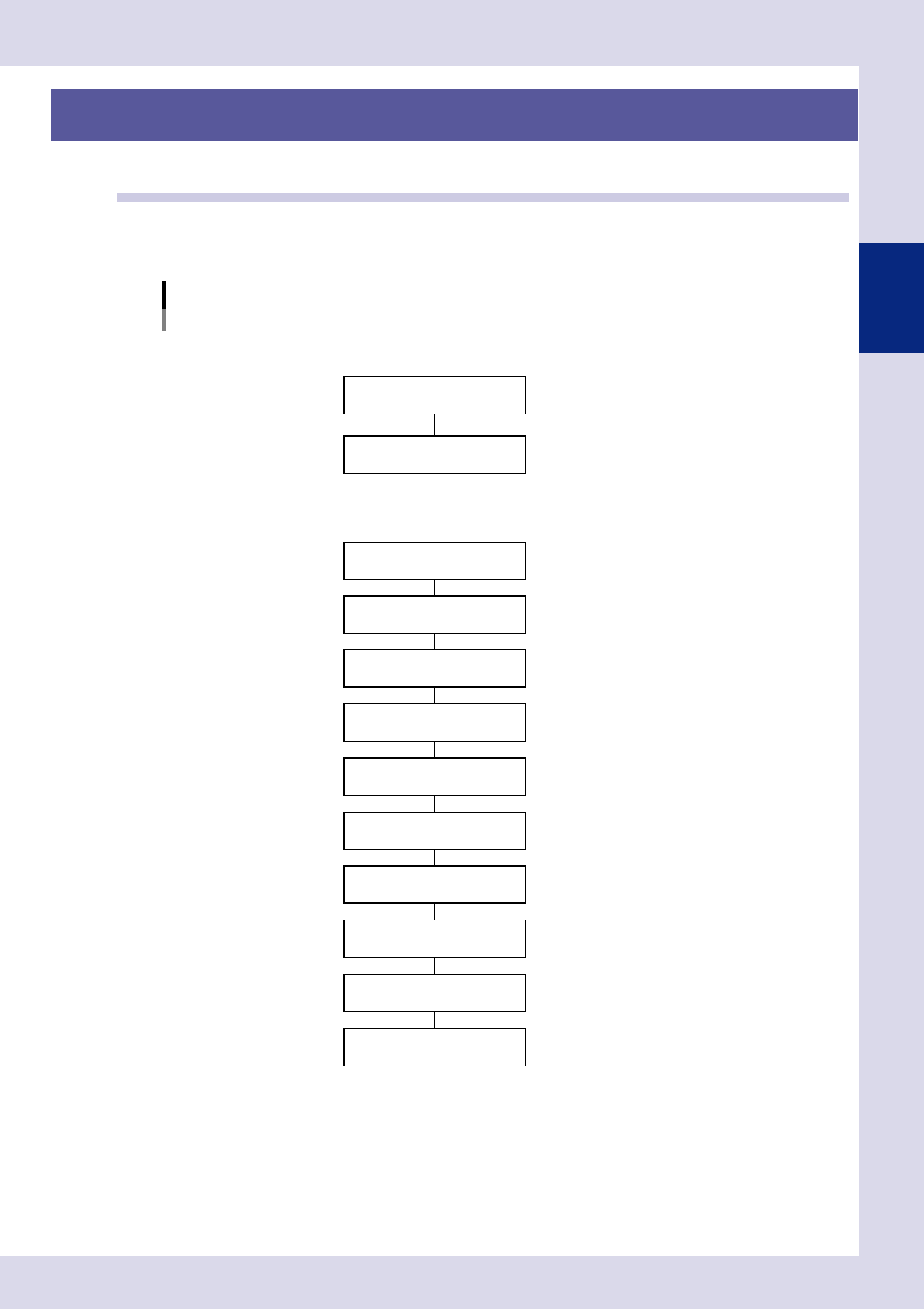
2. Creating inspection programs
This section describes how to create inspection programs for inspection machines from mounter mount data.
2.1 Flowchart for creating an inspection program
Press the [Convert] button at the "Setup" screen to convert YAMAHA mounter mount data to an inspection
program. Inspection programs are created by pasting parts libraries to mounting positions. Mount data for third
party mounters is converted to inspection programs after first converting it to YAMAHA mounter data format.
Flowchart for creating an inspection program
Convert to inspection data
Create full board image
Conversion to YAMAHA mounter data
NConversion from YAMAHA mounter data
Font file creation
NConversion from third party mounter data
* Set libraries if not all parts have been registered in libraries.
F"Common Factory Tools Function" manual
Set fiducial marks
Set views
Set bad marks
Set steps (inspection areas)
Library deployment *
Inspection data complete
Check board inspection
Data tuning
F See Chapter 2, "2.2 Data conversion".
FSee Chapter 2, "2.3 Creating a full board image".
F See Chapter 2, "2.4.1 Fiducial mark settings".
F See Chapter 2, "2.5.2 Bad mark settings".
F See Chapter 2, "2.6 View settings".
F See Chapter 2, "2.7 Step settings".
23212-P6-00