YSI_Prog_E.pdf - 第78页
2-7 2 Inspection data creation and tuning n Fillet • Quantity solder check (solder amount check) T his inspection can be used to detect the fillet area, and determines whether a fillet is formed or not based on that resu…
2-6
2
Inspection data creation and tuning
n
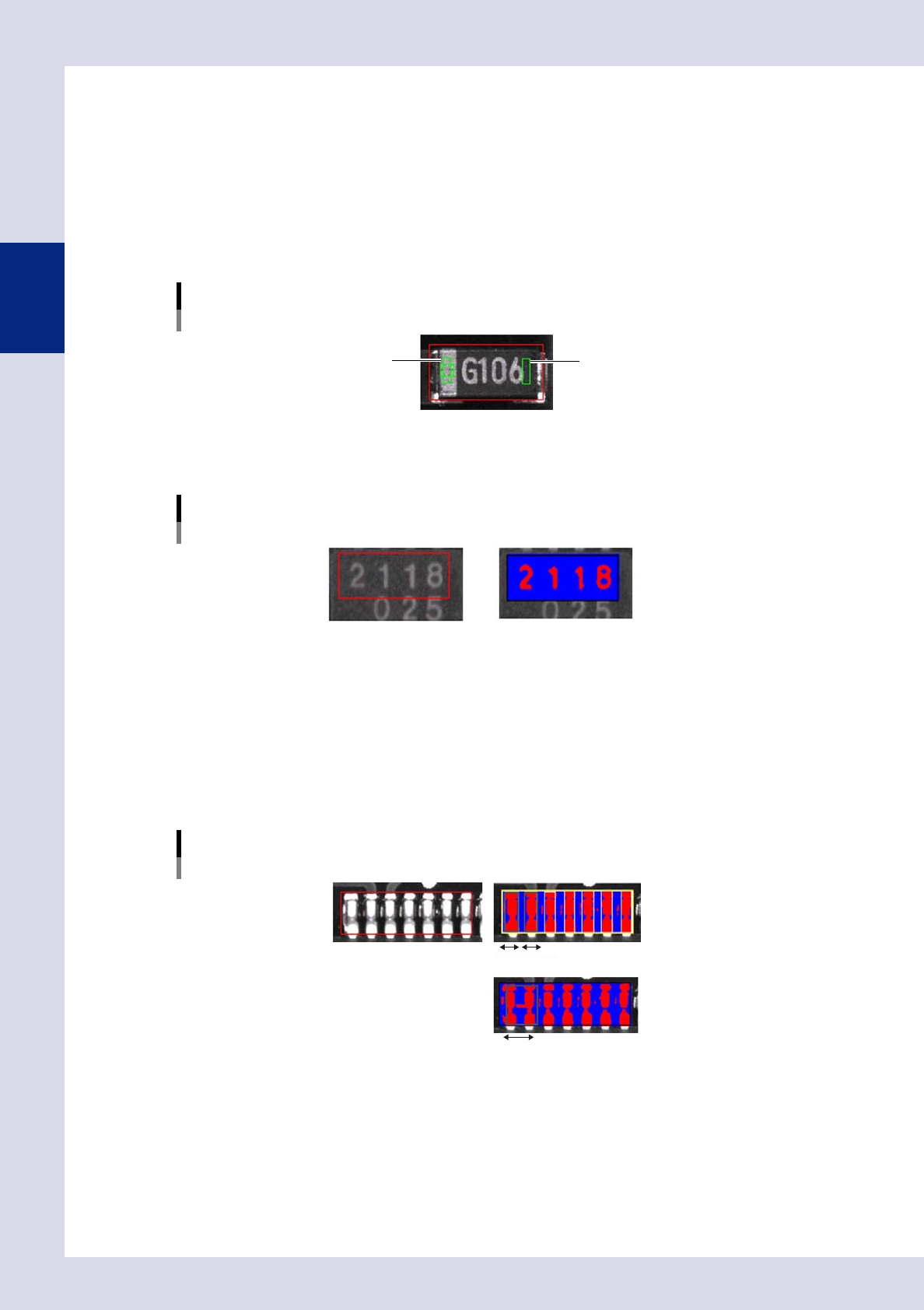
Polarity
One of 3 inspection modes is used, depending on the part type.
•
Polarity check
This inspection mode detects the polarity mark on a part, and determines the polarity based on the area and size of
the mark.
•
Comparison
This inspection mode subtracts the brightness level of one location from that of another location on a part, and
determines the polarity based on the result.
Comparison
1
2
23208-P6-00
•
Character recognition
Characters are detected, and judgment is made based on the character angle.
Character recognition
23209-P6-00
n
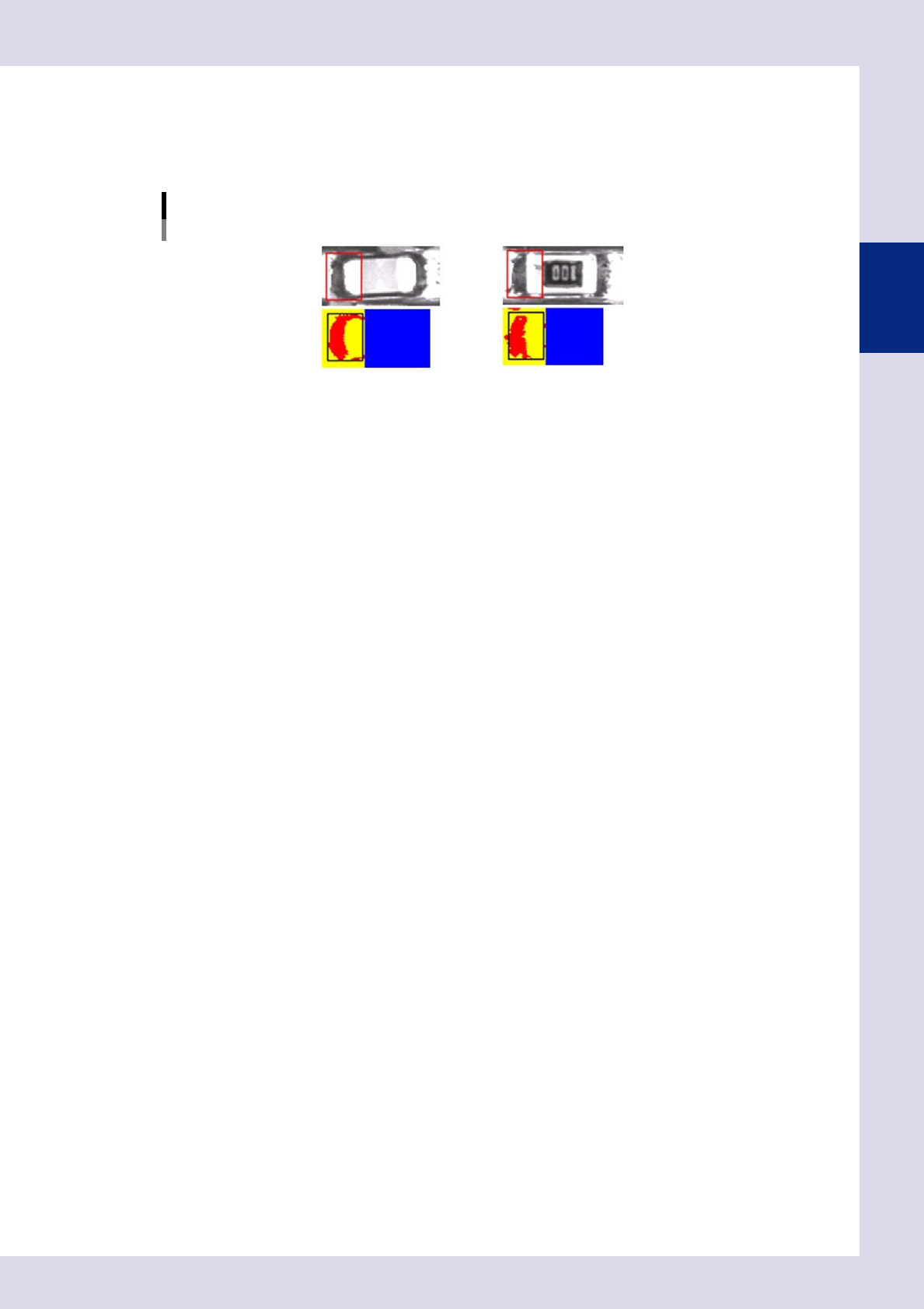
Bridge
•
Lead Check
One of 3 inspections modes is used, depending on the inspection location. It is recommended to test at the maximum
allowable size.
1. Maximum Acceptable Size
This is used for the inspection of bridges between leads on IC parts and so on.
Individual leads and solder inside the inspection frame are detected, and judgment is made based on the vertical and
horizontal sizes.
Maximum Acceptable Size
OK part
Bridge
23210-P6-00
2. Area
This parameter is used to detect the area of each lead to determine whether a solder bridge is formed between leads.
3. Pin Count (Lead Count)
This parameter is used for bridge inspections between leads of 3-pin and 5-pin transistors, etc.
2-7
2
Inspection data creation and tuning
n
Fillet
•
Quantity solder check (solder amount check)
This inspection can be used to detect the fillet area, and determines whether a fillet is formed or not based on that
result.
Quantity solder check (solder amount check)
23211-P6-00
2-8
2
Inspection data creation and tuning
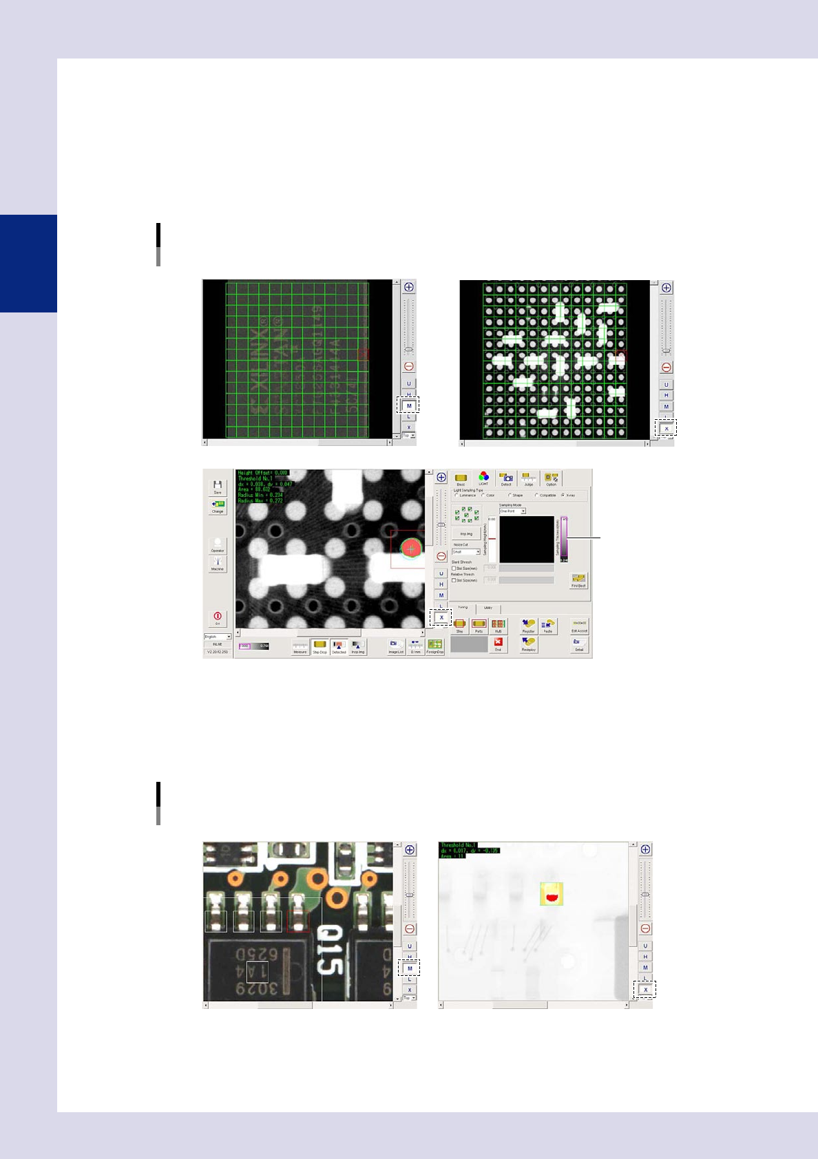
1.3.2 Inspection with X-ray camera
n
Solder inspection of lower surface electrode parts
•
Ball joint check
Inspection is performed with X-ray horizontal tomographic images obtained with digital laminography. Solder is detected
from X-ray horizontal images of joint surfaces on lower surface electrode parts, and judgment is made based on the
detected surface area and radius.
Ball joint check
Optical M lighting image: Displays BGA upper surface
X-ray image: Displays parts on upper/lower surface of board
X-ray image: Balls only detected by setting solder ball height for inspection height
Threshold slide bar
24203-P6-00
n
Back fillet
Inspection is performed with X-ray images taken from above.
•
Solder quantity check
Lead parts back fillet is detected from X-ray images, and judgment is made based on the detected surface area.
Solder quantity check
Optical M lighting image X-ray image: Back fillet detection
24204-P6-00