YSI_Prog_E.pdf - 第201页
4-41 4 Inspection status 5 Perform a step test. 1. Press the [Step] button to per form a test for the created step. T est results and detection data are displayed when testing is complete. 2. Take a n ote of and check th…
4-40
4
Inspection status
3
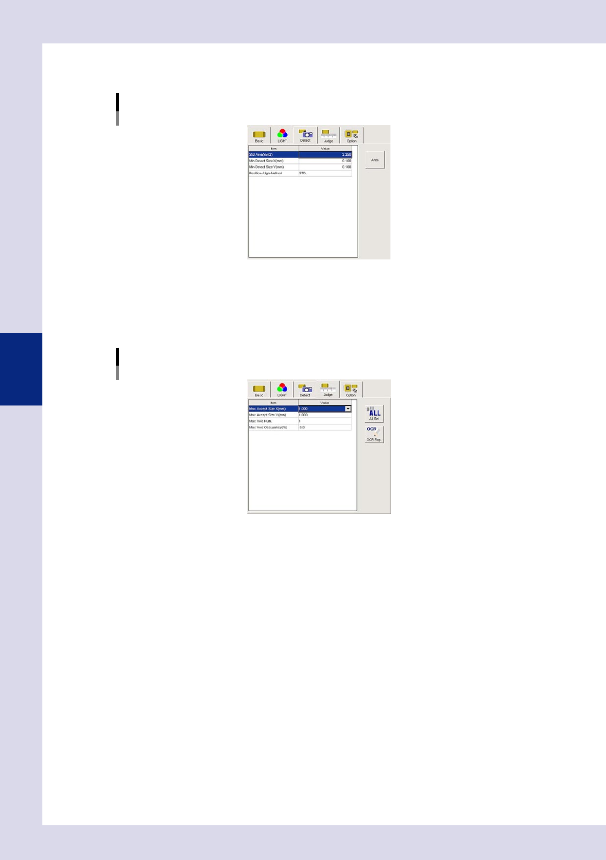
Set the "Detect" parameters.
Open the "Detect" tab and set the following parameters.
"Detect" parameters
Status: Void Check
24460-P6-00
Minimum Detectable Size X, Y (mm)
Set the minimum inspection object size.
4
Set the "Judge" parameters.
Open the "Judge" tab and set the following parameters.
"Judge" parameters
Status: Void Check
24461-P6-00
Max Accept Size X, Y (mm)
An NG result is judged if the detected area X and Y sizes exceed these values.
Max Void Num.
An NG result is judged if the detected number of voids exceeds this value.
Max Void Occupancy (%)
An NG result is judged if the percentage (%) relative to the step area in the detected void area exceeds
this value.
4-41
4
Inspection status
5
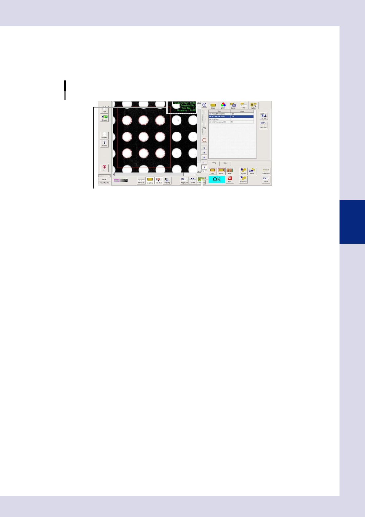
Perform a step test.
1. Press the [Step] button to perform a test for the created step. Test results and detection data are
displayed when testing is complete.
2. Take a note of and check the detection data, and then press the [End] button. When doing so,
there is no problem if the test result is "NG".
Screen after a step test is finished
Test resultDisplays detected data.
24462-P6-00
Detection data
Height Offset= : This is the height offset value used to correct board warp.
Threshold No. : This is the threshold No. applied to inspection.
Void Num.= : This is the number of detected voids.
Occupancy= : This is the void occupancy ratio.
6
Review each parameter and perform a step test again.
If the test result is judged incorrectly, review all parameters.
4-42
4
Inspection status
1.15 Height measurement (option)
This inspection status can be used if equipped with the optional laser height sensor. The height of the
inspection object is measured using the laser height sensor to check whether the result lies within the standard.
After measuring with the board surface and so on as the reference height at "Height Measure" screen, the
height of the inspection object position is measured, and the difference between the reference height is taken
as the parts height. For details, see "Laser Height Sensor" at the end of the Operator's Manual.
1
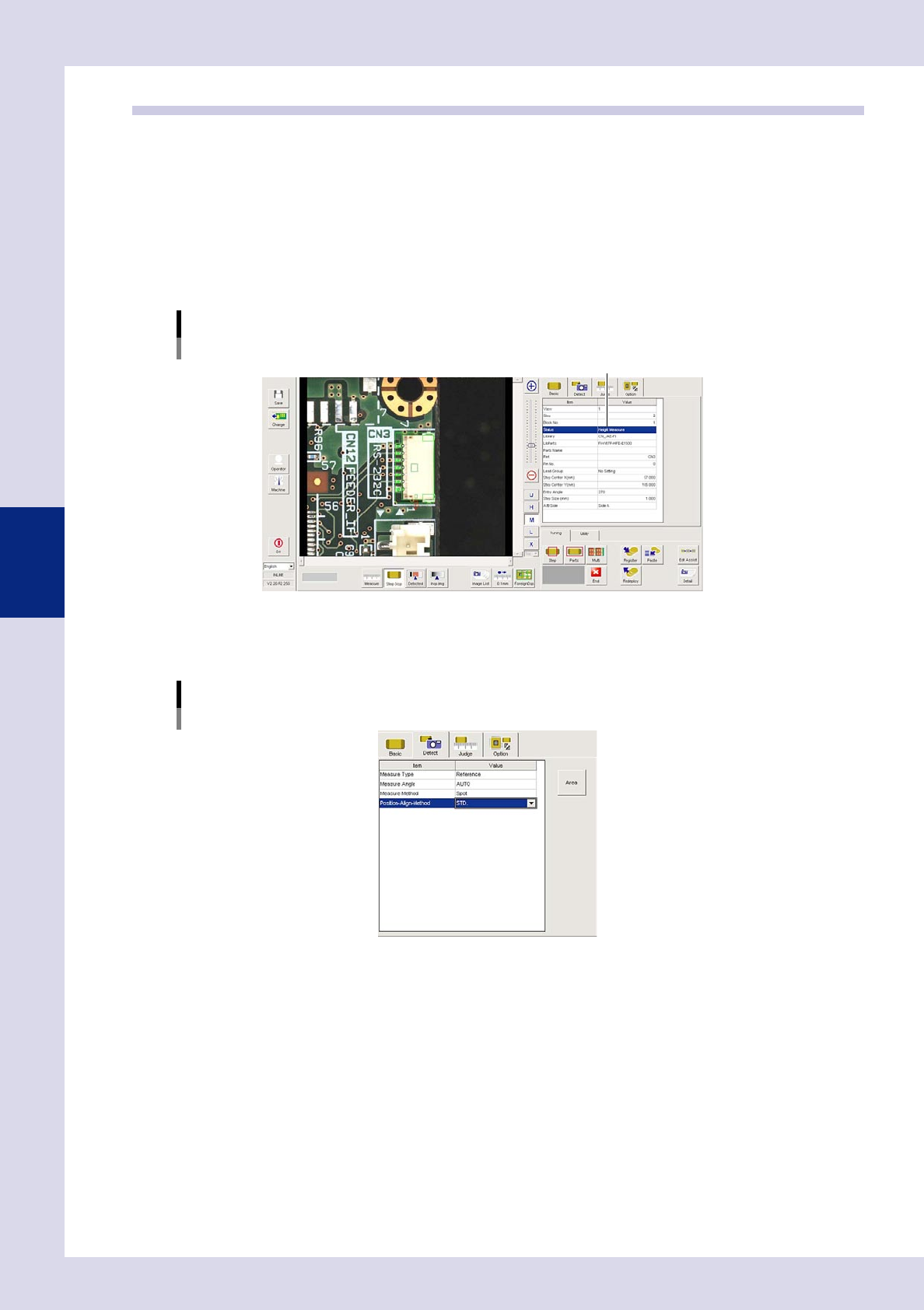
Make a "step" setting for reference height measurement.
1. Create a step frame.
2. Open the "Basic" tab, and set the "Status" in the basic parameters to "Height measure".
Status (Inspection mode)
Height Measure
Set to "Height Measure".
24463-P6-00
2
Set the "Detect" parameters.
Open the "Detect" tab and set the following parameters.
[Detect] tab
24464-P6-00
Measure Type
Select "Reference" from the drop-down list.
Measure Angle
Select the laser beam emission direction (angle) when measuring the parts height as the laser unit
rotates from a drop-down list.
If "AUTO" is selected, the laser emission direction will be the part outer direction.