YSI_Prog_E.pdf - 第186页
4-26 4 Inspection status Memor y No. Select an arbitrary value from the dr op-down list. "1" is selected here. 4 C reate a "step" on the dark side. 1. Select the step created at Step 1, and then copy …
4-25
4
Inspection status
1.9 Comparison
This inspection status is used to inspect polarity and so on based on whether the difference in luminance
between two locations lies within the standard range. Three steps are set for comparison inspection, with
luminance measurement performed first at a bright location, and then at a dark location. Finally, the difference
between the two luminance values is calculated, and a judgment is made on whether the value lies within the
standard. The following description takes a luminance difference comparison as an example, however, the
same settings should be specified even when inspecting differences in thickness with the YSi-X.
n
NOTE
If specifying settings for comparison with the YSi-X, thickness is measured at two locations with similar settings, and
finally, the difference between the two thicknesses is calculated to judge whether the value lies within the standard.
1
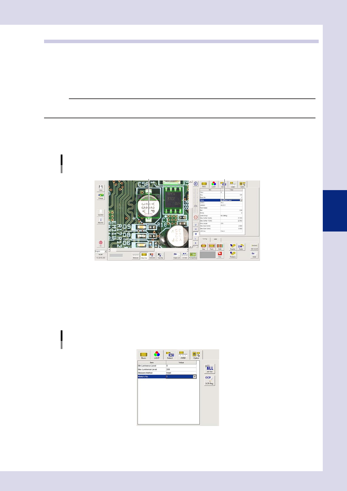
Create a "step" on the bright side.
1. Create a step frame.
2. Open the "Basic" tab, and set the "Status" in the basic parameters to "Brightness Leve".
Status (Inspection mode)
Brightness Level
Set to "Brightness Level".Create a step frame in a bright location.
24436-P6-00
2
Set the "LIGHT" parameters.
1. Open the "LIGHT" tab and select "Luminance" at "Light Sampling Type".
2. Press the button to the right of the sampling light value field to open the sampling light list, select
"Mb+Lb" from the list, and then press the [OK] button.
3
Set the "Judge" parameters.
Open the "Judge" tab and set the following parameters.
"Judge" parameters
Status: Brightness Level
24437-P6-00
Minimum Luminance Level
Select "0" from the drop-down list.
Maximum Luminance Level
Select "255" from the drop-down list.
4-26
4
Inspection status
Memory No.
Select an arbitrary value from the drop-down list. "1" is selected here.
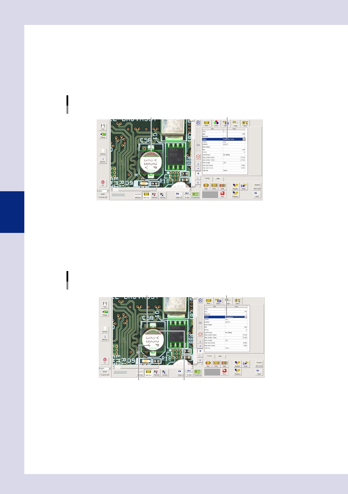
4
Create a "step" on the dark side.
1. Select the step created at Step 1, and then copy and paste the step.
2. Move the pasted step to the position when the part is rotated 180°. Select the step, right-click, and
open the context menu. By selecting a "Step rotation" of "180°", the step moves to the position when
the part is rotated 180°.
Creating a step
"Brightness Level"Create a "step" on dark side.
24438-P6-00
5
Set the "Memory No." in the judgment conditions parameters.
Select a number other than the number set at Step 3 from the drop-down list. "2" is selected here.
6
Create a comparison step.
1. Select the step created at Step 4, and then copy and paste the step.
2. The frame of the pasted step is changed to a different shape in order to distinguish it from the
luminance level steps, and then moves close to the two luminance level steps.
Creating a comparison step
Set to "Comparison".Create a step frame with a different shape.
"Brightness Level" step frame "Brightness Level" step frame
24439-P6-00
4-27
4
Inspection status
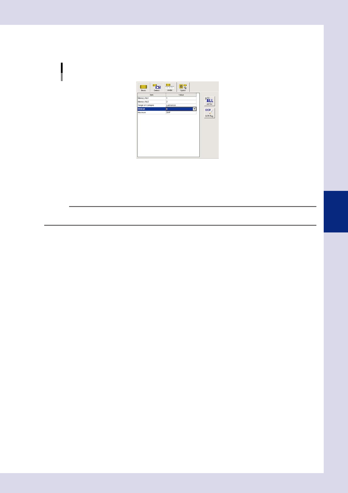
7
Set the basic parameters and judgment conditions parameters.
1. Open the "Basic" tab, and set the "Status" in the basic parameters to "Comparison".
2. Open the "Judge" tab and set the following items.
"Judge" parameters
Status: Comparison
24440-P6-00
Memory No1
Select memory No. "1" set at Step 2.
Memory No2
Select memory No. "2" set at Step 5.
TIP
Inspection is performed at comparison steps with difference in luminance obtained by subtracting the "Memory No2"
luminance from "Memory No1" luminance.
Target of Compare
Luminance
Performs a comparison with the difference in the luminance measurement results for steps set at the
memory No. settings.
Thickness (YSI-X)
Performs a comparison with the difference in the thickness measurement results for steps set at the
memory No. settings.
8
Perform a "step" test.
1. Press the [Step] button to perform a test for the created step. Test results and detection data are
displayed when testing is complete. When doing so, there is no problem if the test result is "NG".
Detection data
Difference =: This is the difference in luminance between two measured steps.
2. Take a note of and check the detection data, and then press the [End] button.
9
Set the "Min Area" and "Max Area" in the "Judge" parameters.
Set by referring to the inspection data Difference.
Minimum
Enter approximately 80% of the Difference. An NG result is judged if the difference in luminance is less
than this value.
Maximum
Enter approximately 120% of the Difference. An NG result is judged if the difference in luminance is
greater than this value.
0
Perform a step test again.
1. Press the [Step] button at the "Tuning" tab again to perform a step test.
2. Take a note of and check the detection data, and then press the [End] button.
3. If the test result is not judged correctly, review all parameters while referring to the detection data.