User Manual - SIPLACE Glue Feedeer.pdf - 第13页
2 General 2.2 Module Description User Manual SIPLACE Glue Feeder 05/2020 13 2.2 Module Description 2.2.1 Overview Fig.2: Overview of Glue Feeder 1. Connection for external compressed air supply 10. Cartridge holder for …

2 General
2.1 Workflows - Typical Scenarios
12 User Manual SIPLACE Glue Feeder 05/2020
Example
The following data is entered in the component shape which describes a 1206 chip component:
●
The position of the glue dot i.e. in the center of the component body
●
The size of the glue dot (diameter in mm)
●
You need to specify whether the glue dot is to be checked by the Vision inspection system. If
yes, you will also need to set the Vision system with the teach function (illumination etc.)
●
However, since not all components of type 1206 are usually glued, you need to define which
specific component numbers of this type are to be glued. For example, component number
123456, a 1206 100 ohm resistor should be glued.
●
In the placement list, you can then define which placement positions for this component
123456 actually need to be glued because, for example, they are on the underside of a board
which has been wave soldered (scenario b ).
Once all these definitions have been recorded and therefore all conditions fulfilled, a glue dot is ap-
plied to this component at the programmed placement position. This glue dot can, depending on its
diameter, be made up of one or more individual glue dots. In the jet dispense method, each shot of
glue applies a nearly constant volume of glue from the nozzle to the target medium.
Setup
As soon as at least one component which needs a glue dot is defined in a placement program, the
product setup will require a Glue Feeder. The Glue Feeder is configured on the same changeover
table as those components which need to be glued. If you need to glue more components than you
have locations on one changeover table or if you need to apply glue to components requiring differ-
ent placement heads on separate machines, you will need to set up multiple Glue Feeders on indi-
vidual changeover tables. Only one Glue Feeder can be configured for each placement head.
Only one Glue Feeder of the same glue type can be set up at any one machine.
When configuring a Glue Feeder, we recommend that you set it up in a fixed position at the center
of the table. If you need to glue several different components, this then gives the shortest possible
travel paths for the placement head. This central position also gives large components in particular
the greatest freedom, for example when a long connector needs a glue dot at the ends and the
middle. If you only need to glue a few components, the feeder modules for these components
should be placed as near as possible to the Glue Feeder.
Setting up the Glue Feeder
Before a Glue Feeder is configured, make sure that all parts which come into contact with the glue
have been cleaned correctly and that all these parts are correctly fitted into place after cleaning. A
suitable cartridge (for which the use before date has not expired) with glue is screwed into the Glue
Feeder. The Glue Feeder is then placed on the changeover table track described in the setup and
locked into place (logged in). After this, the Glue Feeder is connected to the compressed air supply
of the machine and to the safety circuit of the machine.
For a detailed description of how to commission the Glue Feeders, see section 3 "Initial Opera-
tion" [}23].
2 General
2.2 Module Description
User Manual SIPLACE Glue Feeder 05/2020 13
2.2 Module Description
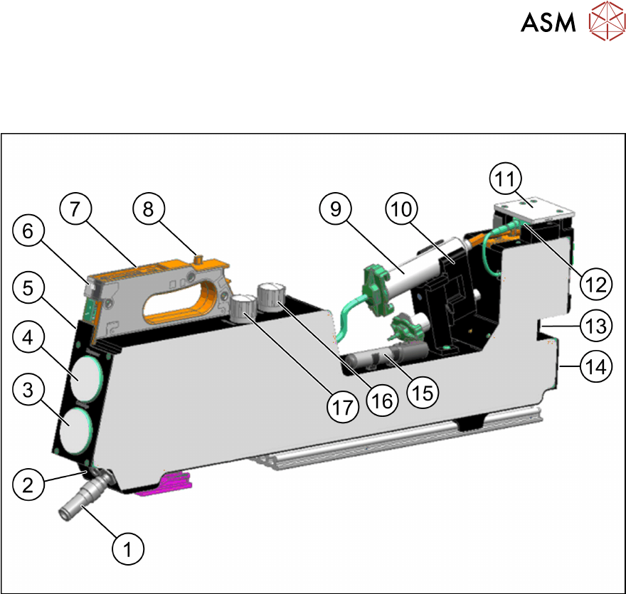
2.2.1 Overview
Fig.2: Overview of Glue Feeder
1. Connection for external compressed air
supply
10. Cartridge holder for 10 ml-/ 30 ml cart-
ridges
2. Connection to machine safety circuit
3. Manometer for current pressure at the
cartridge
11. Nozzle
12. Nozzle heating
4. Manometer for current pressure at the jet
valve
13. Setting screw for the spring pre-tension at
the jet valve
5. Removal handle
6. Status display LED 14. EDIF energy and data interface
7. Control panel 15. Special tool
8. Back centering pin 16. Pressure reducer for pressure at jet valve
of dispenser nozzle
9. Glue cartridge
17. Pressure reducer for pressure at cartridge
Item no. 03088129-xx
2 General
2.2 Module Description
14 User Manual SIPLACE Glue Feeder 05/2020
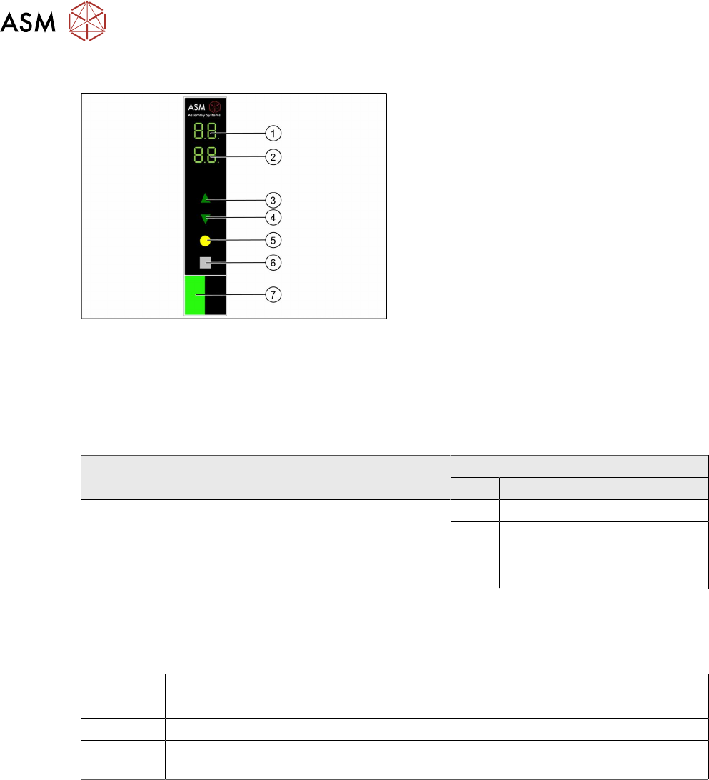
2.2.2 Displays and Controls
1. 7 segment display 1/2
2. 7 segment display 3/4
3. Button to increase value
4. Button to decrease value
5. Button to save set value
6. Button to change to submenu
7. Status display LED
The Glue Feeder has a main menu and submenu for setting the nominal temperature. After switch-
on, the main menu is automatically shown.
To switch over to the submenu, press the gray button. The nominal temperature can be set using
the arrow buttons (3, 4). The main menu is automatically shown again 60 seconds after the last
press of a button.
Overview of 7 segment displays for individual operating states (with error states)
Operating state 7 segment display
No. Display value/symbol
Main menu is active, the Glue Feeder is ready for opera-
tion, the temperature is in the working range.
1/2 Actual temperature
3/4 Nominal temperature
The menu for setting the nominal temperature of the glue
has been selected.
1/2 t E (temperature)
3/4 Nominal temperature
All temperatures are shown in °C. The resolution is 1°C.
Status display LED
The status display LED shows the various operating states.
OFF The Glue Feeder is not needed for the current product or has no electricity supply.
GREEN The Glue Feeder is needed for the current product and there is no error present.
RED An error has occurred which requires action by the operator.
ORANGE Warning (e.g. the safety cover is fitted at the front, on the Glue Feeder, over the
nozzle)
The Glue Feeder always switches the status display LED to ORANGE if the safety cover is on the
jet valve. The station software may overwrite the Glue Feeder display if the machine cover is
closed although the safety cover is still on the jet valve.
For further information about the error displays, see section 6 "Troubleshooting " [}93].