User Manual - SIPLACE Glue Feedeer.pdf - 第27页
3 Initial Operation 3.2 Positioning/Removing the Glue Feeder User Manual SIPLACE Glue Feeder 05/2020 27 Removing the Glue Feeder ► Press the release handle (1) under the status dis- play LED (2) at the rear end of the Gl…
3 Initial Operation
3.2 Positioning/Removing the Glue Feeder
26 User Manual SIPLACE Glue Feeder 05/2020
3.2 Positioning/Removing the Glue Feeder
CAUTION
When using a needle nozzle, fit the safety cover during set up
If you are using the Glue Feeder together with a needle nozzle, fit the safety cover on the
dispenser nozzle to protect it while you are fitting or removing the Glue Feeder. The fragile
needle nozzle protrudes slightly and might be damaged without the safety cover.
Setting up the Glue Feeder
The Glue Feeder is positioned in the same way as an X feeder module. The width of the Glue
Feeder is the same as a 44 mm X feeder module and it occupies 5 tracks at the location.
NOTICE
Location recommendation
A gantry can only work with one Glue Feeder. The programmer needs to make sure that
the required components are configured at the same placement location as the Glue
Feeder.
The number of location tracks on either side of the Glue Feeder which are blocked from use
will vary according to the machine used. Try to position the Glue Feeder as near to the cen-
ter of the location as possible.
NOTICE
Protect the reject bin from glued components
While setting up the Glue Feeder, components and glue dots are checked and then any
glued components are disposed of into the reject bin. Components can also be sent to the
reject bin during the production process.
To protect the reject bin from contamination with glued components, place a cloth in the
bottom of the reject bin. This should be replaced from time to time.
NOTICE
Do not place linear feeder modules directly next to a Glue Feeder!
The vibration of a linear feeder which is directly next to the Glue Feeder can have a negat-
ive effect on the target accuracy when gluing the components.
Do NOT place any linear feeders directly next to the Glue Feeder. Leave at least one track
free to the left and right of the Glue Feeder or set the linear feeder up at another location.
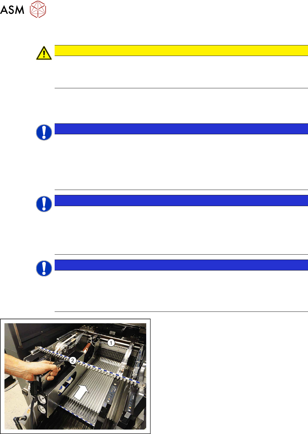
► Position the Glue Feeder with the front sliding
guide onto the Omega profile for the required
track at the location.
► Vertically push the feeder module forward on the
guide until the front centering pin (1)
engages at
the location.
► Make sure that the rear centering pin (2) is in the
correct recess of the rear centering bar that cor-
responds to the front centering pin.
The login procedure will be started. The status display at the rear end of the feeder module will light
up green when the login procedure has been completed successfully, the feeder module has been
included in the current setup and installed on the correct track and the position of the nozzle, plus
its height, has been successfully measured.
3 Initial Operation
3.2 Positioning/Removing the Glue Feeder
User Manual SIPLACE Glue Feeder 05/2020 27
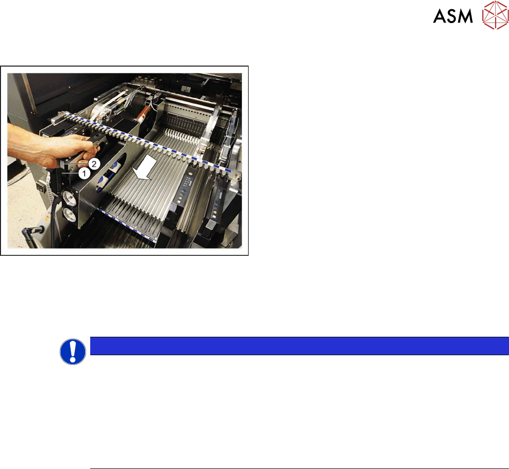
Removing the Glue Feeder
► Press the release handle (1) under the status dis-
play LED (2)
at the rear end of the Glue Feeder.
The log off procedure is started for the Glue Feeder, the status display is switched off and the
removal handle will protrude. All key data will be saved in the Glue Feeder. The Glue Feeder will
then be automatically logged off the FCU and the FCU will open the mechanical lock at the loca-
tion. As soon as the status displays are dark, the log off procedure has been completed.
► Now use the removal handle to pull the feeder module out of the location.
NOTICE
Repeating log on and off
If you wait for too long when removing the Glue Feeder (> approx 5 seconds), the status
display will shine red and you will need to log the Glue Feeder back on again.
► Press the removal handle in the Glue Feeder.
The log on procedure for the Glue Feeder will start.
► Wait until the log on procedure is completed and the status display lights up green.
► Press the removal handle at the rear end of the Glue Feeder again and then pull the
Glue Feeder out of the location, as soon as the status display extinguishes.
3 Initial Operation
3.3 Connecting the Glue Feeder to the Safety Circuit
28 User Manual SIPLACE Glue Feeder 05/2020
3.3 Connecting the Glue Feeder to the Safety Circuit
NOTICE
Connection to safety circuit already present?
If the machine does not yet have a connection to the safety circuit, you will need to fit this
first. You will find a retrofit description in the appropriate retrofit kit for your machine.
The integration of the Glue Feeder into the safety circuit of the machine ensures that, when the
machine cover is open, the Glue Feeder can only dispense glue if the safety cover is fitted correctly
into place on the jet valve. This is an important safety measure which safeguards the operator from
being hit by a shot of glue and injured.
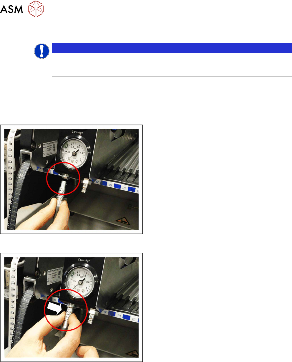
Connecting the safety circuit
► Plug the connector from the safety circuit into the
connection shown in the diagram.
Make sure that the red dot on the connector and
the red dot on the connection are in line (one
above the other).
Disconnecting the safety circuit
► To disconnect the Glue Feeder form the safety
circuit, grip the removal ring on the LEMO con-
nector, as marked in the diagram, and pull the
connector down and off.