User Manual - SIPLACE Glue Feedeer.pdf - 第20页
2 General 2.2 Module Description 20 User Manual SIPLACE Glue Feeder 05/2020 2.2.8 Settings Table The following table should help you to find the optimum Glue Feeder setting for your requirements. Die to the various diffe…

2 General
2.2 Module Description
User Manual SIPLACE Glue Feeder 05/2020 19
2.2.7 System Requirements and General Restrictions
Preconditions
The Glue Feeder can only be used on SIPLACE machines with the station software from 706.1 and
in SIPLACE Pro from version 10.1 with the X Feeder interface.
Furthermore, the machine must be fitted with a connection to the safety circuit and a connection to
the compressed air supply. The following retrofit sets are available for fitting the required items:
●
Retrofit set Glue Feeder SX12 / DX12, item no. 03091006-xx
●
Retrofit kit for Glue Feeder SX4 / DX4, item no. 03091007-xx
●
Retrofit kit for Glue Feeder X-Series, item no. 03091008-xx
Restrictions
A gantry can only work with one Glue Feeder.
The Glue Feeder is not designed for use of
●
Solder paste
●
Anaerobic curing glues (such as superglue)
●
UV-curing adhesives
When using UV-curing adhesives, the user is responsible for ensuring that the nozzle opening
of the glue is not exposed to UV light.
Radiation with UV light can lead to unintentional curing of the glue in the nozzle.
●
Transparent adhesive
In some cases, it might not be possible to inspect transparent (clear) adhesives with the Vis-
ion system.
Other restrictions
●
The jet valve must not dry out i.e. be operated without adhesive.
●
Bridging the safety circuit is prohibited.
●
The Glue Feeder may only be cleaned using the cleaning agents prescribed by the glue man-
ufacturer or ASMAS.
●
The programming of glue dots which exceed the diameter of the component at any point is
prohibited (risk of contamination!)
●
When applying glue to narrow edges – even when these are within the component body - only
dispense glue dots which have been adjusted accordingly in their size, otherwise there is a
risk of glue dot division and uncontrolled spurting away of glue at the sides.
●
MELF and SOD (glass diode) components
Due to their round bodies, MELF and SOD (glass diode) components are in principle not suit-
able for glue application. The round body shape poses an increased risk of placement head
contamination. We therefore recommend that these components are not glued or only glued
after thorough assessment of the risks.
2 General
2.2 Module Description
20 User Manual SIPLACE Glue Feeder 05/2020
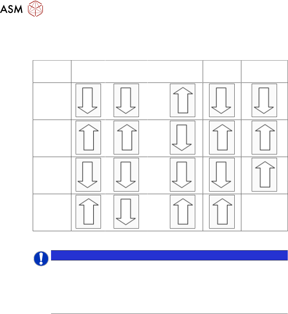
2.2.8 Settings Table
The following table should help you to find the optimum Glue Feeder setting for your requirements.
Die to the various different adhesives this table can not be seen as exhaustive and is only intended
as an overview data based on experience.
Pressure
at
jet valve
Pressure at
cartridge
Plunger setting
in mm
Temperat-
ure
(heating)
Diameter
of nozzle
Smaller
glue dots
>0.6
Larger
glue dots
<0.6
Avoid
satellite form-
ation
<0.6
Avoid
glue residues
on the nozzle
>0.6
--
2.2.9 Setting the Jet Plunger
NOTICE
Increased wear when pressure is higher
The jet plunger is factory set to 60N (corresponds to 0.6mm plunger setting). This setting
allows the SIPLACE Glue Feeder to process common epoxy resin-based SMD adhesives
reliably and in high quality.
After changing this setting, you may need to adjust the characteristics at the station.
Please note that higher settings (>60N) will lead to increased wear of the jet plunger and
particularly to the dispenser nozzle.
We recommend that you check the plunger setting in the following cases:
●
General check of factory setting to 0.6 mm
●
Same setting when using multiple Glue Feeders at your site
●
Optimization of glue dot quality
General check of factory setting to 0.6 mm
If the quality of the glue dots should deteriorate, despite regular maintenance, and if this can not be
remedied with the temperature and pressure settings, the plunger setting can be checked using the
plunger measuring system "Measuring system - plunger adjustment", item no. 03126592-01.
Checking and setting of the jet plunger is described in the service manual for the Glue Feeder item
no. 00197278-xx, chapter "Replacing Spare Parts", in the section about "Jet Valve P-Dot".
Same setting when using multiple Glue Feeders at one site
To avoid differences in the size and quality of the glue dots between the individual Glue Feeders,
the Glue Feeders can be checked with the plunger measurement system and adjusted, if neces-
sary.

2 General
2.2 Module Description
User Manual SIPLACE Glue Feeder 05/2020 21
Optimization of glue dot quality
If you increase the plunger setting >0.6mm (>60N ), this also increases the spring pre-tension in
the jet valve. The consequence of this is that the glue dot is dispensed with more power. This can
lead to improvements when using adhesives which have a high viscosity.
If you increase the plunger setting, less adhesive flows into the dispenser nozzle between the indi-
vidual "shots". This means that, although the number of shots remains the same, a lower volume of
adhesive is applied to the component. Depending on the viscosity of the glue and the type of
component surface, this might cause the glue dot to have a wider diameter. The cause for this is
that the glue is dispensed with greater power and therefore at a higher speed. This change must be
taken into account when setting the characteristic line, in relation to the glue dot check by the Vis-
ion system.
Furthermore, a higher plunger setting will lead to flatter glue dots, if the number of shots remains
the same. Check whether the contact between the glue dot and the board is present and increase
the number of shots where necessary.
We recommend that the plunger setting only be increased as far as really needed. Changes to the
plunger setting are only advisable if you are using other glues than those recommended by us. Ob-
serve in particular the information about increased wear of the jet plunger and at the dispenser
nozzle.
If you reduce the plunger setting <0.6mm (<60N), the characteristics will change in the opposite
direction to that described above. To make sure that the shape of your glue dot is acceptable, you
should not set the jet plunger to <0.2mm (<20N).
The jet plunger setting range is between 0.2mm and 1.5mm (20N to 150N).