User Manual - SIPLACE Glue Feedeer.pdf - 第25页
3 Initial Operation 3.1 Inserting the Cartridge User Manual SIPLACE Glue Feeder 05/2020 25 ► Fit the cartridge adapter at the straight points onto the back of the cartridge and press on as far as the stop. ► Turn the car…
3 Initial Operation
3.1 Inserting the Cartridge
24 User Manual SIPLACE Glue Feeder 05/2020
3.1 Inserting the Cartridge
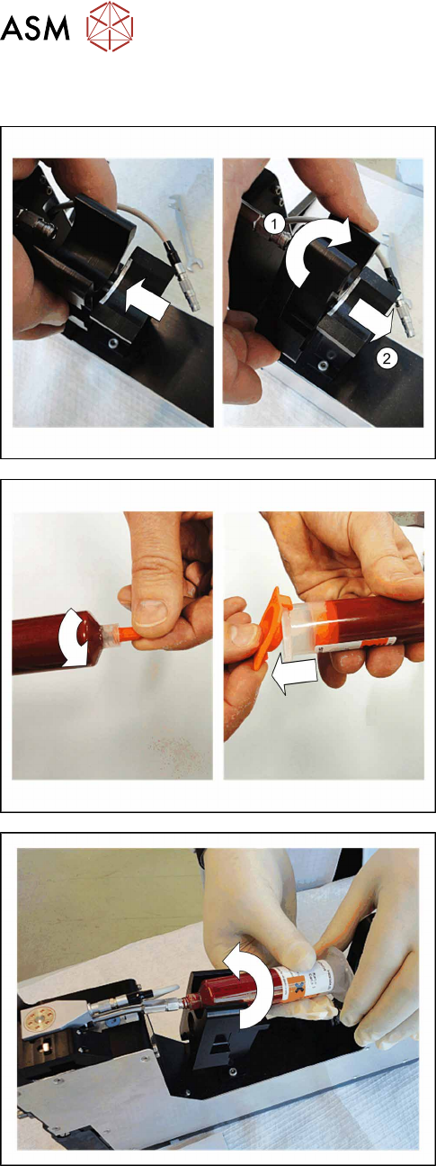
Two sizes of cartridge can be used with the Glue
Feeder.
► Adjust the cartridge holder to the size of the cart-
ridge to be used (10 or 30 ml).
1. Then pull out the cartridge holder.
2. Turn the cartridge holder so that the required size
is at the top.
3. Let the cartridge holder engage audibly.
► Screw the front cap off the cartridge.
► Remove the back cap from the cartridge.
► Hold the cartridge against the feed pipe and
screw it on to the pipe straight.
3 Initial Operation
3.1 Inserting the Cartridge
User Manual SIPLACE Glue Feeder 05/2020 25
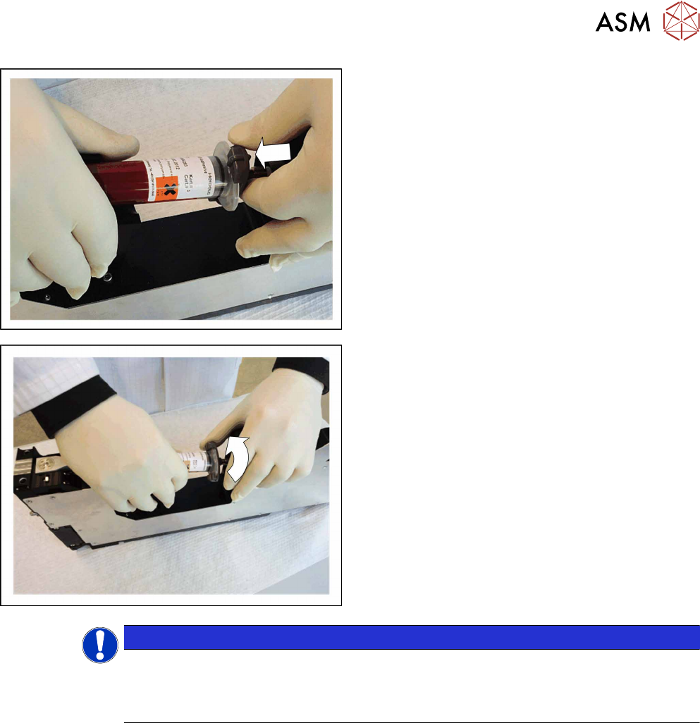
► Fit the cartridge adapter at the straight points
onto the back of the cartridge and press on as far
as the stop.
► Turn the cartridge adapter clockwise as far as the
stop.
► Make sure that the O-ring on the cartridge adap-
ter is completely flush against the inside of the
cartridge and seals it. If not, the required cart-
ridge pressure will not form.
To make it easier to insert the adapter with the
O‑ring, you can grease the O-ring slightly (Tur-
motemp II/400 CL2).
NOTICE
Predosing
Although you have inserted the cartridge, the Glue Feeder is still not ready for use. You first
need to position the Glue Feeder at the required location and pre-dose the glue unit (feed
pipe, jet block and dispenser nozzle) i.e. fill it with glue.
3 Initial Operation
3.2 Positioning/Removing the Glue Feeder
26 User Manual SIPLACE Glue Feeder 05/2020
3.2 Positioning/Removing the Glue Feeder
CAUTION
When using a needle nozzle, fit the safety cover during set up
If you are using the Glue Feeder together with a needle nozzle, fit the safety cover on the
dispenser nozzle to protect it while you are fitting or removing the Glue Feeder. The fragile
needle nozzle protrudes slightly and might be damaged without the safety cover.
Setting up the Glue Feeder
The Glue Feeder is positioned in the same way as an X feeder module. The width of the Glue
Feeder is the same as a 44 mm X feeder module and it occupies 5 tracks at the location.
NOTICE
Location recommendation
A gantry can only work with one Glue Feeder. The programmer needs to make sure that
the required components are configured at the same placement location as the Glue
Feeder.
The number of location tracks on either side of the Glue Feeder which are blocked from use
will vary according to the machine used. Try to position the Glue Feeder as near to the cen-
ter of the location as possible.
NOTICE
Protect the reject bin from glued components
While setting up the Glue Feeder, components and glue dots are checked and then any
glued components are disposed of into the reject bin. Components can also be sent to the
reject bin during the production process.
To protect the reject bin from contamination with glued components, place a cloth in the
bottom of the reject bin. This should be replaced from time to time.
NOTICE
Do not place linear feeder modules directly next to a Glue Feeder!
The vibration of a linear feeder which is directly next to the Glue Feeder can have a negat-
ive effect on the target accuracy when gluing the components.
Do NOT place any linear feeders directly next to the Glue Feeder. Leave at least one track
free to the left and right of the Glue Feeder or set the linear feeder up at another location.
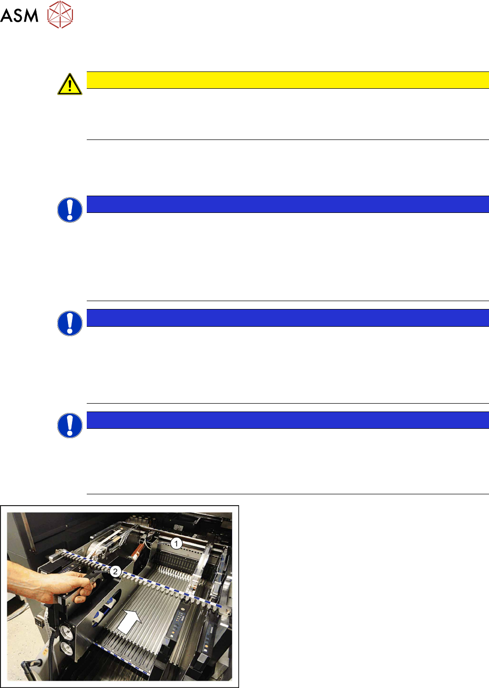
► Position the Glue Feeder with the front sliding
guide onto the Omega profile for the required
track at the location.
► Vertically push the feeder module forward on the
guide until the front centering pin (1)
engages at
the location.
► Make sure that the rear centering pin (2) is in the
correct recess of the rear centering bar that cor-
responds to the front centering pin.
The login procedure will be started. The status display at the rear end of the feeder module will light
up green when the login procedure has been completed successfully, the feeder module has been
included in the current setup and installed on the correct track and the position of the nozzle, plus
its height, has been successfully measured.