User Manual - SIPLACE Glue Feedeer.pdf - 第15页
2 General 2.2 Module Description User Manual SIPLACE Glue Feeder 05/2020 15 2.2.3 Technical Data Operating pressure of Glue Feeder Connection to the machine: External connection: max. 5.6 bar max. 7.5 bar The manufacture…
2 General
2.2 Module Description
14 User Manual SIPLACE Glue Feeder 05/2020
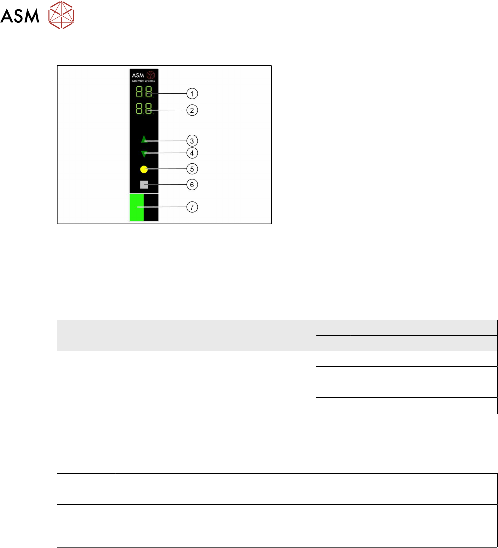
2.2.2 Displays and Controls
1. 7 segment display 1/2
2. 7 segment display 3/4
3. Button to increase value
4. Button to decrease value
5. Button to save set value
6. Button to change to submenu
7. Status display LED
The Glue Feeder has a main menu and submenu for setting the nominal temperature. After switch-
on, the main menu is automatically shown.
To switch over to the submenu, press the gray button. The nominal temperature can be set using
the arrow buttons (3, 4). The main menu is automatically shown again 60 seconds after the last
press of a button.
Overview of 7 segment displays for individual operating states (with error states)
Operating state 7 segment display
No. Display value/symbol
Main menu is active, the Glue Feeder is ready for opera-
tion, the temperature is in the working range.
1/2 Actual temperature
3/4 Nominal temperature
The menu for setting the nominal temperature of the glue
has been selected.
1/2 t E (temperature)
3/4 Nominal temperature
All temperatures are shown in °C. The resolution is 1°C.
Status display LED
The status display LED shows the various operating states.
OFF The Glue Feeder is not needed for the current product or has no electricity supply.
GREEN The Glue Feeder is needed for the current product and there is no error present.
RED An error has occurred which requires action by the operator.
ORANGE Warning (e.g. the safety cover is fitted at the front, on the Glue Feeder, over the
nozzle)
The Glue Feeder always switches the status display LED to ORANGE if the safety cover is on the
jet valve. The station software may overwrite the Glue Feeder display if the machine cover is
closed although the safety cover is still on the jet valve.
For further information about the error displays, see section 6 "Troubleshooting " [}93].
2 General
2.2 Module Description
User Manual SIPLACE Glue Feeder 05/2020 15
2.2.3 Technical Data
Operating pressure of Glue Feeder
Connection to the machine:
External connection:
max. 5.6 bar
max. 7.5 bar
The manufacturer's information on the operating medium
also apply.
Pay attention to the compressed air specifications for the
placement machine.
Length 584.9 mm
Height 199.5 mm
Width 57.6 mm, corresponds to 5 tracks, each with 8mm
Weight 4.6 kg
Diameter
smallest possible single dot *
0.7 - 0.8 mm (+/- 0.1mm)
Diameter
dot made with 5 shots *
1.0 mm (+/- 0.2 mm)
Height
single dot *
0.15 mm (+/- 0.02 mm)
Height
dot made with 5 shots *
0.2–0.3mm
* for 100 µm nozzle diameter and use of glue Heraeus PD205A-Jet(at53°C) or Loc-
tite3621(at53°C)
Manufacturer's data for the jet valve (not for the overall system)
Valve type 16 NC
Dosage volume 10 – 200 nl per cycle
Viscosity range 50 - 200,000 mPas (thixotrope)
Dosage accuracy > 99 % (dosage tolerance < 1 %)
Dosage frequency Typically 15 - 20 ms or 50 - 67 Hz, maximum 150 Hz
Materials which touch fluid Stainless steel, non-corrosive 1.4305; hard metal K10 (WC
+Co); NBR
Operating medium Filtered compressed air, unoiled, filtration fineness 40µm
Operating pressure 2 ..... 8bar
Switching time < 1 ms
Control 24 V, SPS compatible
Service life >10
8
switching cycles
Weight 270 g
Ambient temperature -5 ..... +40°C
Max. heating temperature 70°C
2 General
2.2 Module Description
16 User Manual SIPLACE Glue Feeder 05/2020
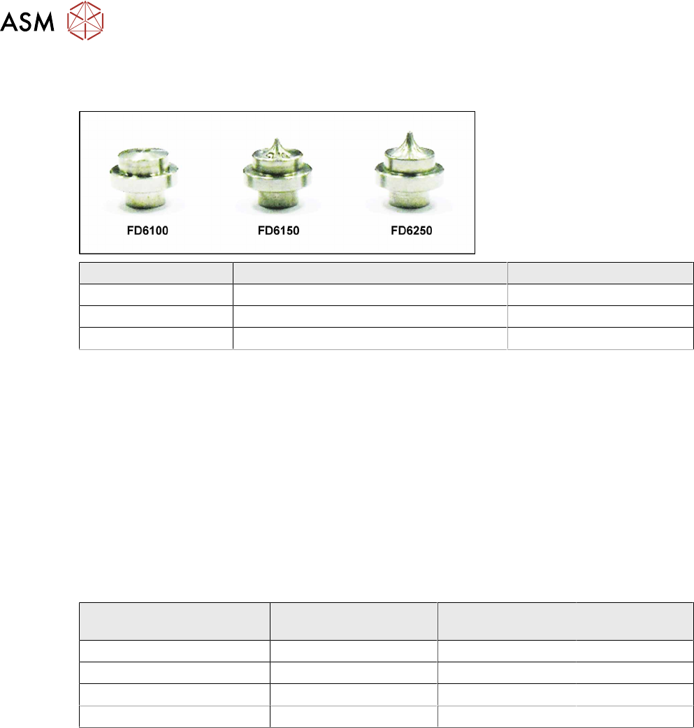
2.2.4 Overview of the Nozzles
This section gives you an overview of the currently available dispenser nozzles.
Item number Designation Dispenser nozzle shape
03094220-xx Flat jet FD6100 (100 microm.) 1014
03094182-xx Needle jet ND6150 (150 microm.) 1016
03120082-xx Needle jet ND6250 (250 microm.) 1019
2.2.5 Overview of Glues
The Glue Feeder currently supports the following adhesives:
●
Heraeus PD-205A
●
Loctite 3621
●
Loctite D125F
●
Delo Monopox MK096
As the various glues have different properties, you need to individually adjust the pressure at the
cartridge, at the jet valve and the temperature of the glue for each type of glue. The temperature
can be set via the station software or, if needed, directly at the Glue Feeder.
The following table shows an overview of the optimum values for the individual glues.
Glue Pressure at cartridge Pressure at jet
valve
Nominal tem-
perature
Heraeus PD-205A 1.5bar 3.0bar 53°C
Loctite 3621 / 3609 / 3619 1.5bar 3.0bar 53°C
Loctite D125F 3bar 4.5bar 53°C
Delo Monopox MK096 1.5bar 3.0bar 40°C
General notes about temperature
The temperature of the glue in the jet block is read by a sensor and then adjusted to the set TAR-
GET value. If no TARGET value has been set, the glue temperature will be set to the default value
of 40°C
. The temperature can be set from 40°C to a maximum of 70°C.
The permissible tolerance range for dispensing is ±3°C of the set TARGET value. The Glue Feeder
sends a signal to the machine whenever this range is left or entered again. Dispensing is not pos-
sible outside the tolerance range.
The temperature is increased using the nozzle heating function on the jet block. A reduction in tem-
perature is only reached passively by cooling down via the ambient temperature. To save glue, the
nozzle heating is switched on automatically if there is a processing break of longer than 10 minutes
at the Glue Feeder.