SONY机开关EAO-Series-14-Full-Data.pdf - 第12页
14 Devices raised mounting 13 06.2007 Continuation see ne xt page Further information in the Techni cal Data and Typical Applications Terminals: S1 = Soldering term inal (also pluggable 2.8 x 0.5 mm) Mounting dimensions …
14
Devices raised mounting
12
06.2007
non-illuminative
Continuation see next page
Switching system: LL = Low level switching element, SA = Snap-action switching element
Contacts: NC = Normally closed, NO = Normally open
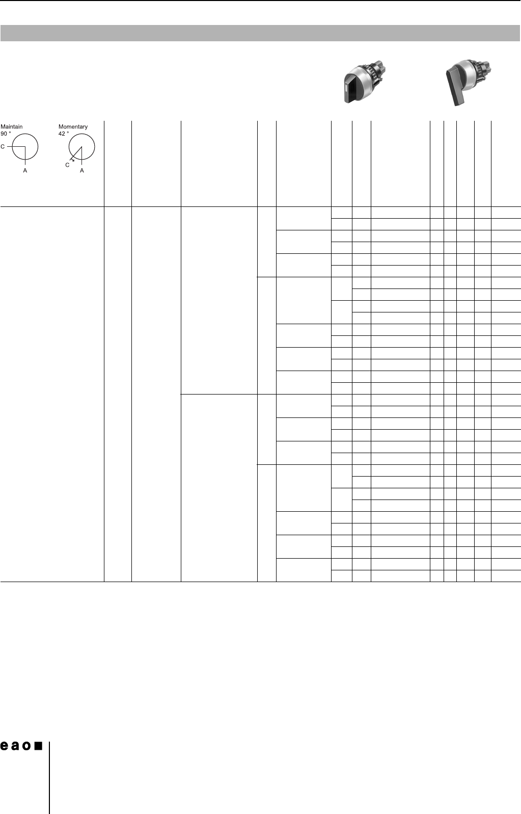
Switching action: MA = Maintained action, M = Momentary action
Terminals: UT = Universal terminal, S = Soldering terminal, S1 = Soldering terminal (also pluggable 2.8 x 0.5 mm)
Component layout from page 36, Mounting dimensions from page 37, Technical drawing from page 38, Circuit drawing from page 48
Selector switch 2 positions
0
Front protection
Front ring Lever
Switching system
Contacts
Switching action
Terminals
Ø 29 mm
Typ-Nr.
Component layout
Mounting dimensions
Technical drawing
Circuit drawing
e
Selector switch
2 positions
Position A : Basic position
IP 67 Aluminium
natural
Plastic black long LL 1 NC + 1 NO MA UT 14-572.0360 1 4 19 29 0.025
MUT14-567.0360 1 4 19 22 0.025
2 NC MA UT 14-571.0360 1 4 19 28 0.025
MUT14-566.0360 1 4 19 21 0.025
2 NO MA UT 14-570.0360 1 4 19 30 0.025
MUT14-565.0360 1 4 19 23 0.025
SA 1 NC + 1 NO MA S 14-556.02502 428240.024
S1 14-556.0220 428240.024
MS14-551.02502 428170.024
S1 14-551.0220 428170.024
2 NC + 2 NO MA S 14-557.02502 428250.026
MS14-552.02502 428180.026
3 NC + 3 NO MA S 14-558.02502 428260.028
MS14-553.02502 428190.028
4 NC + 4 NO MA S 14-559.02502 428270.030
MS14-554.02502 428200.030
Plastic black short LL 1 NC + 1 NO MA UT 14-522.0360 1 4 20 29 0.025
MUT14-517.0360 1 4 20 22 0.025
2 NC MA UT 14-521.0360 1 4 20 28 0.025
MUT14-516.0360 1 4 20 21 0.025
2 NO MA UT 14-520.0360 1 4 20 30 0.025
MUT14-515.0360 1 4 20 23 0.025
SA 1 NC + 1 NO MA S 14-506.02502 429240.024
S1 14-506.0220 429240.024
MS14-501.02502 429170.024
S1 14-501.0220 429170.024
2 NC + 2 NO MA S 14-507.02502 429250.026
MS14-502.02502 429180.026
3 NC + 3 NO MA S 14-508.02502 429260.028
MS14-503.02502 429190.028
4 NC + 4 NO MA S 14-509.02502 429270.030
MS14-504.02502
429200.030
14
Devices raised mounting
13
06.2007
Continuation see next page
Further information in the Technical Data and Typical Applications
Terminals: S1 = Soldering terminal (also pluggable 2.8 x 0.5 mm)
Mounting dimensions from page 37, Technical drawing from page 38, Circuit drawing from page 48
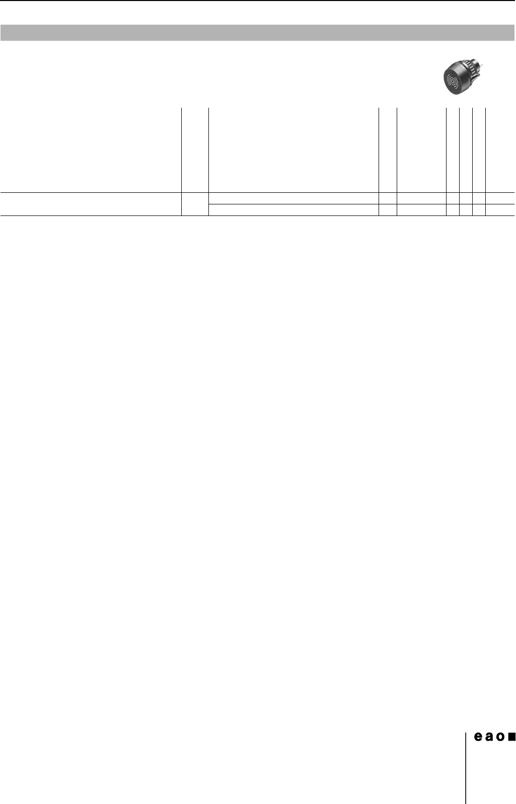
Buzzer
Front protection
Front cap
Terminals
Ø 29 mm
Typ-Nr.
Mounting dimensions
Technical drawing
Circuit drawing
e
Buzzer
Operation voltage 24 VDC
IP 65 Brass chromium-plated S1 14-810.902 4110.016
Plastic black S1 14-810.002 4110.016
14
Devices flush mounting
14
06.2007
Essential Accessories:
d Front bezel set, flush mounting page 21
d Lens plastic page 19
d Marking plate for Lens plastic and metal page 20
d Single-LED page 25
Continuation see next page
Terminals: S = Soldering terminal, S1 = Soldering terminal (also pluggable 2.8 x 0.5 mm), UT = Universal terminal
Component layout from page 36, Mounting dimensions from page 37, Technical drawing from page 38, Circuit drawing from page 48
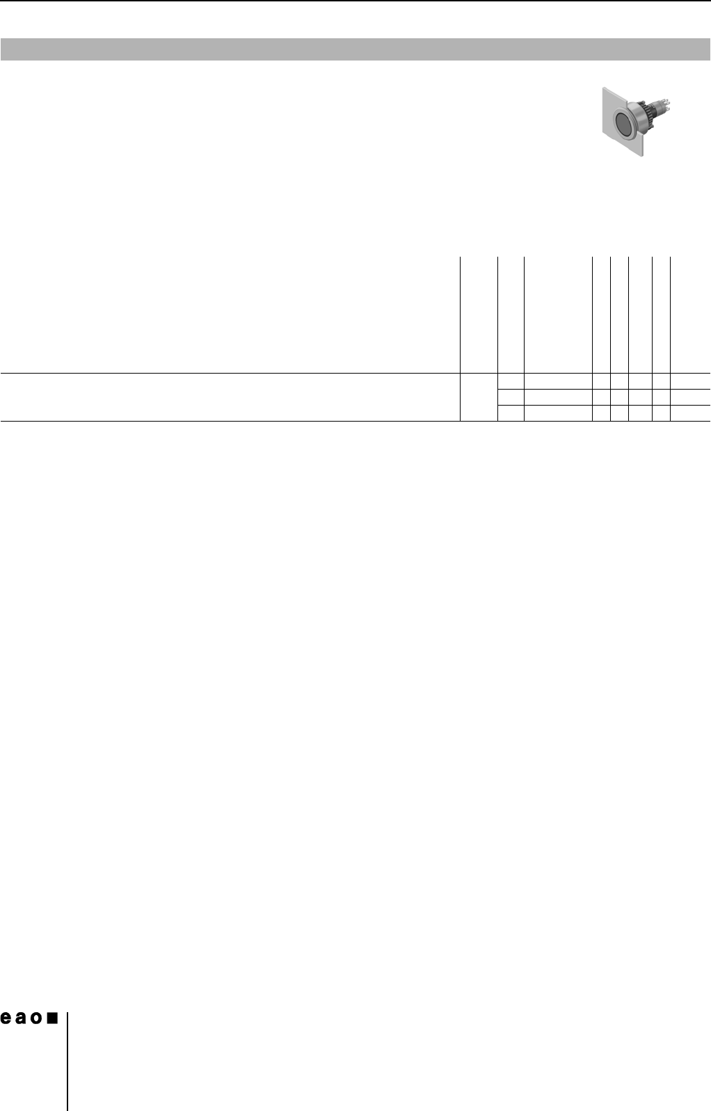
Indicator actuator, flush mounting
Front protection
Terminals
Ø 29 mm
Typ-Nr.
Component layout
Mounting dimensions
Technical drawing
Circuit drawing
e
Indicator actuator, flush mounting IP 67 S 14-040.005 1 30 3 0.050
S1 14-040.002 1 30 3 0.050
UT 14-041.006 1 1 30 3 0.050