SONY机开关EAO-Series-14-Full-Data.pdf - 第15页
14 Devices flush mounting 16 06.2007 Essential Accessories: d Anti-twist ring, flush mounting page 26 d Front bezel set, flush mounting page 21 Continuation se e next page Keylock switches are supplied with 2 keys. Other…
14
Devices flush mounting
15
06.2007
Essential Accessories:
d Front bezel set, flush mounting page 21
d Lens plastic page 19
d Marking plate for Lens plastic and metal page 20
d Single-LED page 25
Continuation see next page
Switching system: LL = Low level switching element, SA = Snap-action switching element
Contacts: NC = Normally closed, NO = Normally open
Diode (1N 4007): - = without, D = Diode
Switching action: MA = Maintained action, M = Momentary action
Terminals: UT = Universal terminal, S = Soldering terminal, S1 = Soldering terminal (also pluggable 2.8 x 0.5 mm)
Component layout from page 36, Mounting dimensions from page 37, Technical drawing from page 38, Circuit drawing from page 48
Illuminated pushbutton actuator, flush mounting
Front protection
Switching system
Contacts
Diode (1N 4007)
Switching action
Terminals
Ø 29 mm
Typ-Nr.
Component layout
Mounting dimensions
Technical drawing
Circuit drawing
e
Illuminated pushbutton actuator, flush mounting IP 67 LL 1 NC - MA UT 14-476.036 1 1 32 12 0.015
MUT14-436.036 1 1 32 39 0.015
1 NC + 1 NO - MA UT 14-473.036 1 1 32 15 0.015
MUT14-433.036 1 1 32 42 0.015
1 NO - MA UT 14-475.036 1 1 32 14 0.015
MUT14-435.036 1 1 32 41 0.015
2 NC - MA UT 14-472.036 1 1 32 13 0.015
MUT14-432.036 1 1 32 40 0.015
2 NO - MA UT 14-471.036 1 1 32 16 0.015
MUT14-431.036 1 1 32 43 0.015
SA 1 NC + 1 NO 1 D MA UT 14-747.0292 11319 0.014
MUT14-743.0292 1 1 31 36 0.014
2 D MA UT 14-748.0292 1 1 31 10 0.014
MUT14-744.0292 1 1 31 37 0.014
-MAS14-271.0252 132110.013
S1 14-271.022 132110.013
MS14-131.0252 132380.013
S1 14-131.022 132380.013
2 NC + 2 NO 1 D MA UT 14-749.0292 11316 0.016
MUT14-745.0292 1 1 31 33 0.016
2 D MA UT 14-750.0292 11317 0.016
MUT14-746.0292 1 1 31 34 0.016
-MAS14-272.0252 1 32 8 0.015
MS14-132.0252 132350.015
3 NC + 3 NO - MA S 14-273.0252 1 32 5 0.017
MS14-133.0252 132320.017
4 NC + 4 NO - MA S 14-274.0252 1 32 4 0.019
MS14-134.0252 132310.019
14
Devices flush mounting
16
06.2007
Essential Accessories:
d Anti-twist ring, flush mounting page 26
d Front bezel set, flush mounting page 21
Continuation see next page
Keylock switches are supplied with 2 keys.
Other lock numbers on request
Switching system: LL = Low level switching element, SA = Snap-action switching element
Contacts: NC = Normally closed, NO = Normally open
Switching action: MA = Maintained action, M = Momentary action
Terminals: UT = Universal terminal, S = Soldering terminal, S1 = Soldering terminal (also pluggable 2.8 x 0.5 mm)
Component layout from page 36, Mounting dimensions from page 37, Technical drawing from page 38, Circuit drawing from page 48
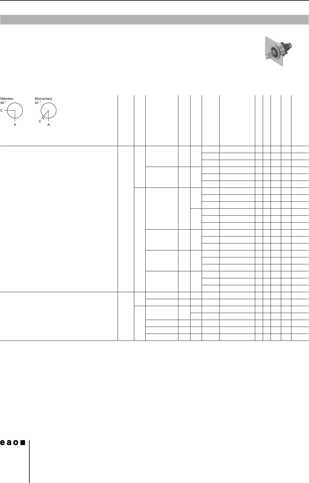
Keylock switch actuator 2 positions, flush mounting
0
Front protection
Switching system
Contacts
Switching action
Terminals
Key remove
Ø 29 mm
Typ-Nr.
Component layout
Mounting dimensions
Technical drawing
Circuit drawing
e
Keylock switch actuator 2 positions, flush
mounting
Position A : Basic position
Position C : Maintained action
Standard lock 1001,
Front : Plastic black
IP 65 LL 1 NC + 1 NO MA UT A 14-415.036K 1133540.030
C 14-418.036K 1133540.030
C + A 14-412.036K 1133540.030
2 NO MA UT A 14-414.036K 1133550.030
C 14-417.036K 1133550.030
C + A 14-411.036K 1133550.030
SA 1 NC + 1 NO MA S A 14-235.025K2 1 33 50 0.029
C 14-335.025K2 1 33 50 0.029
C + A 14-135.025K2 1 33 50 0.029
S1 A 14-235.022K 1 33 50 0.029
C 14-335.022K 1 33 50 0.029
C + A 14-135.022K 1 33 50 0.029
2 NC + 2 NO MA S A 14-236.025K2 1 33 51 0.031
C 14-336.025K2 1 33 51 0.031
C + A 14-136.025K2 1 33 51 0.031
3 NC + 3 NO MA S A 14-237.025K2 1 33 52 0.033
C 14-337.025K2 1 33 52 0.033
C + A 14-137.025K2 1 33 52 0.033
4 NC + 4 NO MA S A 14-238.025K2 1 33 53 0.035
C 14-338.025K2 1 33 53 0.035
C + A 14-138.025K2 1 33 53 0.035
Position A : Basic position
Position C : Momentary action
Standard lock 1001
Front : Plastic black
IP 65 LL 1 NC + 1 NO M UT A 14-438.036K 1133480.030
2 NO M UT A 14-437.036K 1133490.030
SA 1 NC + 1 NO M S A 14-141.025K2 1 33 44 0.029
S1 A 14-141.022K 1 33 44 0.029
2 NC + 2 NO M S A 14-142.025K2 1 33 45 0.031
3 NC + 3 NO M S A 14-143.025K2 1 33 46 0.033
4 NC + 4 NO M S A 14-144.025K2 1 33 47 0.035
14
Devices flush mounting
17
06.2007
Essential Accessories:
d Anti-twist ring, flush mounting page 26
d Front bezel set, flush mounting page 21
Continuation see next page
Switching system: LL = Low level switching element, SA = Snap-action switching element
Contacts: NC = Normally closed, NO = Normally open
Switching action: MA = Maintained action, M = Momentary action
Terminals: UT = Universal terminal, S = Soldering terminal, S1 = Soldering terminal (also pluggable 2.8 x 0.5 mm)
Component layout from page 36, Mounting dimensions from page 37, Technical drawing from page 38, Circuit drawing from page 48
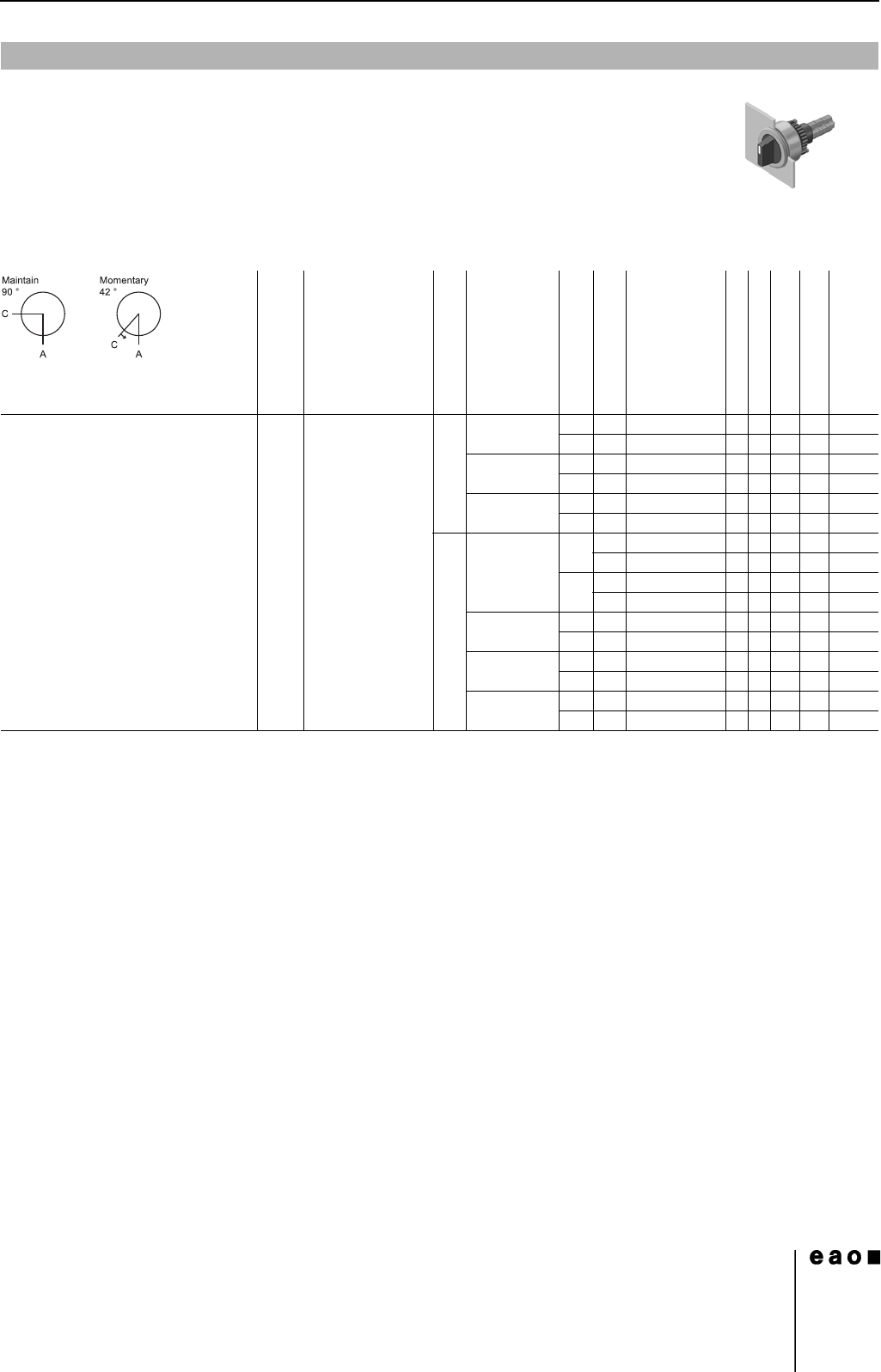
Selector switch actuator 2 positions, flush mounting
0
Front protection
Lever
Switching system
Contacts
Switching action
Terminals
Ø 29 mm
Typ-Nr.
Component layout
Mounting dimensions
Technical drawing
Circuit drawing
e
Selector switch actuator 2 positions,
flush mounting
Position A : Basic position
IP 67 Plastic black short LL 1 NC + 1 NO MA UT 14-522.0360 1 1 34 29 0.025
MUT14-517.0360 1 1 34 22 0.025
2 NC MA UT 14-521.0360 1 1 34 28 0.025
MUT14-516.0360 1 1 34 21 0.025
2 NO MA UT 14-520.0360 1 1 34 30 0.025
MUT14-515.0360 1 1 34 23 0.025
SA 1 NC + 1 NO MA S 14-506.02502 134240.024
S1 14-506.0220 134240.024
MS14-501.02502 134170.024
S1 14-501.0220 134170.024
2 NC + 2 NO MA S 14-507.02502 134250.026
MS14-502.02502 134180.026
3 NC + 3 NO MA S 14-508.02502 134260.028
MS14-503.02502 134190.028
4 NC + 4 NO MA S 14-509.02502 134270.030
MS14-504.02502 134200.030