SONY机开关EAO-Series-14-Full-Data.pdf - 第26页
27 06.2007 14 Accessories Continuation see ne xt page CAUTION A switching process might be rele ased w hen replacing the Lamp/LED ! Grey similar RAL 7035; cover lead-sealable Continuation see ne xt page Openings for cabl…
26
06.2007
14
Accessories
for fitting with series resistors
Continuation see next page
Continuation see next page
Mounting dimensions from page 37
Continuation see next page
Devices 22.5 mm dia. in mounting hole size 30.5 mm dia.
Continuation see next page
With the metal bayonet flange you can use one reduction ring. If you have a plastic bayonet flange you need to install two
reduction rings.
Continuation see next page
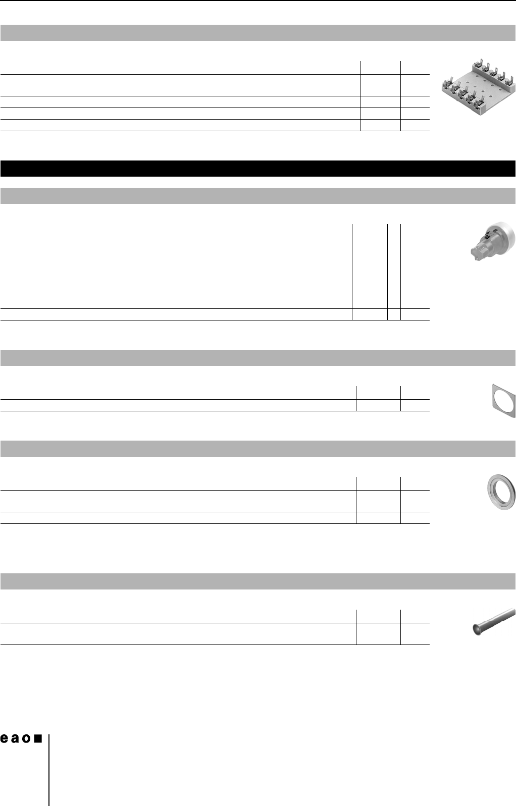
Terminal plate empty
Typ-Nr.
e
Terminal plate empty
10 spaces 125 x 60 x 15 mm
02-912.2 0.045
15 spaces 187.5 x 60 x 15 mm 02-912.3 0.090
20 spaces 250 x 60 x 15 mm 02-912.4 0.095
5 spaces 62.5 x 60 x 15 mm 02-912.1 0.025
Assembling
Positioning insert
Typ-Nr.
Mounting dimensions
e
Positioning insert 14-910 3 0.001
Anti-twist ring, flush mounting
Typ-Nr.
e
Anti-twist ring, flush mounting 704.954.0 0.002
Reducing ring
Typ-Nr.
e
Reducing ring
Aluminium black
704.960.0 0.004
Aluminium natural 704.960.8 0.004
Lens plug for round lens, flush mounting
Typ-Nr.
e
Lens plug for round lens, flush mounting
for mounting and dismantling of Lens round, flush mounting
700.006.0 0.003
27
06.2007
14
Accessories
Continuation see next page
CAUTION
A switching process might be released when replacing the Lamp/LED !
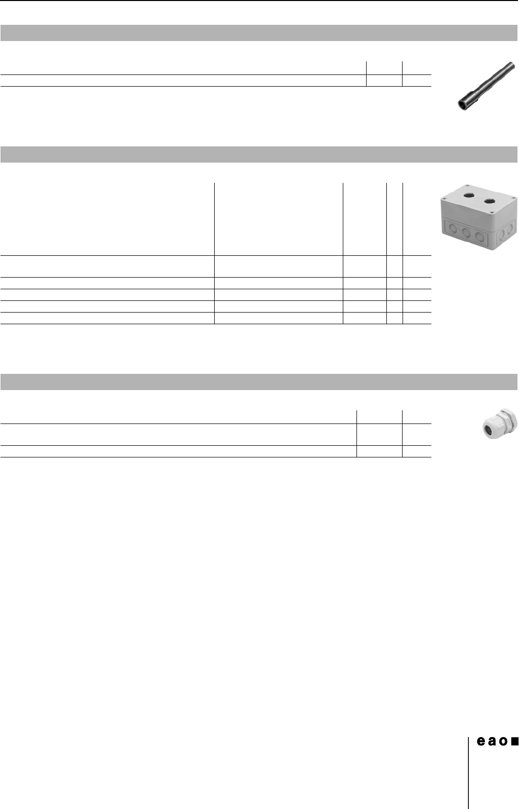
Grey similar RAL 7035; cover lead-sealable
Continuation see next page
Openings for cable gland M16 or M20
Protection class IP 66
Technical drawing from page 38
Continuation see next page
with traction relief; protection degree IP 68
Lamp remover
Typ-Nr.
e
Lamp remover 02-906 0.002
Enclosure
Dimension Typ-Nr.
Technical drawing
e
Enclosure
with mounting hole 1 x 22.5 mm dia., with anti-twist device
L 94 mm, W 94 mm, H 81 mm 704.945.1 11 0.211
with mounting hole 2 x 22.5 mm dia., with anti-twist device L 130 mm, W 94 mm, H 81 mm 704.945.2 12 0.251
with mounting hole 3 x 22.5 mm dia., with anti-twist device L 180 mm, W 94 mm, H 81 mm 704.945.3 13 0.313
with mounting hole 4 x 22.5 mm dia., with anti-twist device L 180 mm, W 182 mm, H 110 mm 704.945.4 14 0.572
with mounting hole 6 x 22.5 mm dia., with anti-twist device L 180 mm, W 182 mm, H 110 mm 704.945.5 15 0.568
Cable gland
Typ-Nr.
e
Cable gland
M16, Plastic grey
61-9481.6 0.007
M20, Plastic grey 704.945.6 0.011

28
06.2007
14
Technical Data
Switching system
Self-cleaning, double-break, snap action switching system (with
contact gap 2 x 0.5 mm).
1 normally closed or 1 normally open contact per element.
Snap-action switching elements with soldering terminals at the
sides: up to 4 switching element can be on a pushbutton (max. 4
normally closed and 4 normally open contacts).
Snap-action switching element with axial plug-in terminals 2.8 mm
stackable, only 1 switching element can be on a pushbutton.
Material
Material of contact
Gold plated silver
Switch housing
Plug-in-/soldering terminal
Diallylphthalate DAP, Polyamide 66, Polysulfone, heat-resistant
and self-extinguishing
Soldering terminal: PA 6.6 Ultramide
Actuator housing
Polyamide
Mechanical characteristics
Terminals
Snap-action switching element with tinned soldering terminals at
the sides:
Max. wire diameter 2 wires à 1.2 mm
max. wire cross-section of stranded cable 1x 1 mm²
Snap-action switching element with axial plug-in terminals, which
can also be used as soldering terminals: Plug-in terminal 2.8 x 0.5
mm
Soldering terminal:
Max. wire diameter 2 wires of 1 mm
Max. wire cross-section of stranded cable 2 x 0.75 mm² or 1 x 1.0
mm²
Actuating torque
Measured at the key or lever of the keylock- or selector switch
2.5 Ncm ... 5.5 Ncm, depending on the number of switching
elements
Actuating force
3.5 ... 5.5 N, depending on the number of switching elements
Actuating travel
0
0
Rebound time
≤5ms
Mechanical lifetime
0
Electrical characteristics
Standards
The devices comply with : EN IEC 61058-1
Rated voltage
250 VAC/DC as per EN IEC 61058-1-15
Contact resistance
New state ≤50 mΩ as per DIN IEC 60512-2-4
Electrostatic discharge
Keylock switch 15 kV
Rated current
5 A
Conventional free air thermal current I
th
5 A
The maximum current in continuous operation and at ambient
temperature not exceeding the quoted maximum values.
Switch rating
250 VAC, 5 A (cosφ 1)
250 VAC, 3 A (cosφ 0,3)
Switch rating AC (cosφ 0,7)
0
Switch rating DC (inductive) L:R = 30 ms
0
Electric strength
3000 VAC, 50 Hz, 1 min. between all terminals and earth, as per
EN IEC 61058-1-15
Isolation resistance
>7 MΩ between the opend contats at 500 VDC, as per
EN IEC 61058-1-15 (reinforced insulation)
Protection class
II
Environmental conditions
Storage temperature
-40 °C ... +85 °C
Service temperature
-25 °C ... +55 °C
For indicators and illuminated pushbuttons mounted as a block,
make sure the heat can escape freely.
Protection degree
as per EN IEC 60529
front side IP 67
Shock resistance
(semi-sinusoidal)
max. 150 m/s², pulse width 11 ms, 3-axis, as per
EN IEC 60068-2-27
Actuator with snap-action switching element
Illuminated pushbutton: 3 mm
Switch actuator 2 positions:
Momentary action 1 x ca. 42° deflection
momentary action
Maintained action 1 x ca. 90° deflection
maintained action
Switch actuator 3 positions:
Momentary action 2 x ca. 42° deflection
momentary action
Maintained action 2 x ca. 90° deflection
maintained action
Momentary action 2 million Cycles of operation
Maintained action 1 million Cycles of operation
Voltage 125 VAC 250 VAC
Current 3 A 2 A
Voltage 24 VDC 60 VDC 110 VDC 220 VDC
Current 2 A 0.7 A 0.2 A 0.1 A