SONY机开关EAO-Series-14-Full-Data.pdf - 第16页
14 Devices flush mounting 17 06.2007 Essential Accessories: d Anti-twist ring, flush mounting page 26 d Front bezel set, flush mounting page 21 Continuation see ne xt page Switching system: LL = Low level switching eleme…
14
Devices flush mounting
16
06.2007
Essential Accessories:
d Anti-twist ring, flush mounting page 26
d Front bezel set, flush mounting page 21
Continuation see next page
Keylock switches are supplied with 2 keys.
Other lock numbers on request
Switching system: LL = Low level switching element, SA = Snap-action switching element
Contacts: NC = Normally closed, NO = Normally open
Switching action: MA = Maintained action, M = Momentary action
Terminals: UT = Universal terminal, S = Soldering terminal, S1 = Soldering terminal (also pluggable 2.8 x 0.5 mm)
Component layout from page 36, Mounting dimensions from page 37, Technical drawing from page 38, Circuit drawing from page 48
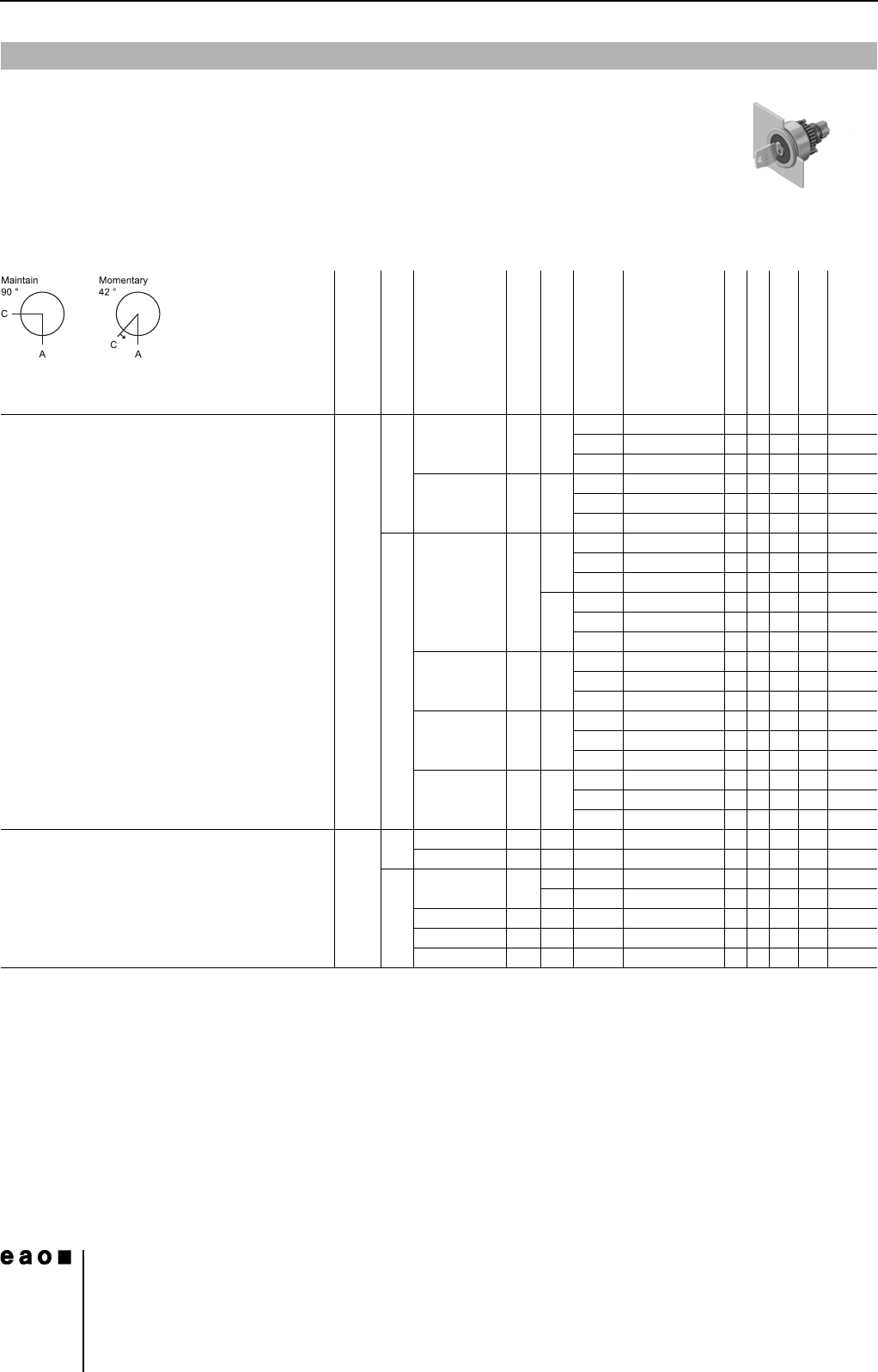
Keylock switch actuator 2 positions, flush mounting
0
Front protection
Switching system
Contacts
Switching action
Terminals
Key remove
Ø 29 mm
Typ-Nr.
Component layout
Mounting dimensions
Technical drawing
Circuit drawing
e
Keylock switch actuator 2 positions, flush
mounting
Position A : Basic position
Position C : Maintained action
Standard lock 1001,
Front : Plastic black
IP 65 LL 1 NC + 1 NO MA UT A 14-415.036K 1133540.030
C 14-418.036K 1133540.030
C + A 14-412.036K 1133540.030
2 NO MA UT A 14-414.036K 1133550.030
C 14-417.036K 1133550.030
C + A 14-411.036K 1133550.030
SA 1 NC + 1 NO MA S A 14-235.025K2 1 33 50 0.029
C 14-335.025K2 1 33 50 0.029
C + A 14-135.025K2 1 33 50 0.029
S1 A 14-235.022K 1 33 50 0.029
C 14-335.022K 1 33 50 0.029
C + A 14-135.022K 1 33 50 0.029
2 NC + 2 NO MA S A 14-236.025K2 1 33 51 0.031
C 14-336.025K2 1 33 51 0.031
C + A 14-136.025K2 1 33 51 0.031
3 NC + 3 NO MA S A 14-237.025K2 1 33 52 0.033
C 14-337.025K2 1 33 52 0.033
C + A 14-137.025K2 1 33 52 0.033
4 NC + 4 NO MA S A 14-238.025K2 1 33 53 0.035
C 14-338.025K2 1 33 53 0.035
C + A 14-138.025K2 1 33 53 0.035
Position A : Basic position
Position C : Momentary action
Standard lock 1001
Front : Plastic black
IP 65 LL 1 NC + 1 NO M UT A 14-438.036K 1133480.030
2 NO M UT A 14-437.036K 1133490.030
SA 1 NC + 1 NO M S A 14-141.025K2 1 33 44 0.029
S1 A 14-141.022K 1 33 44 0.029
2 NC + 2 NO M S A 14-142.025K2 1 33 45 0.031
3 NC + 3 NO M S A 14-143.025K2 1 33 46 0.033
4 NC + 4 NO M S A 14-144.025K2 1 33 47 0.035
14
Devices flush mounting
17
06.2007
Essential Accessories:
d Anti-twist ring, flush mounting page 26
d Front bezel set, flush mounting page 21
Continuation see next page
Switching system: LL = Low level switching element, SA = Snap-action switching element
Contacts: NC = Normally closed, NO = Normally open
Switching action: MA = Maintained action, M = Momentary action
Terminals: UT = Universal terminal, S = Soldering terminal, S1 = Soldering terminal (also pluggable 2.8 x 0.5 mm)
Component layout from page 36, Mounting dimensions from page 37, Technical drawing from page 38, Circuit drawing from page 48
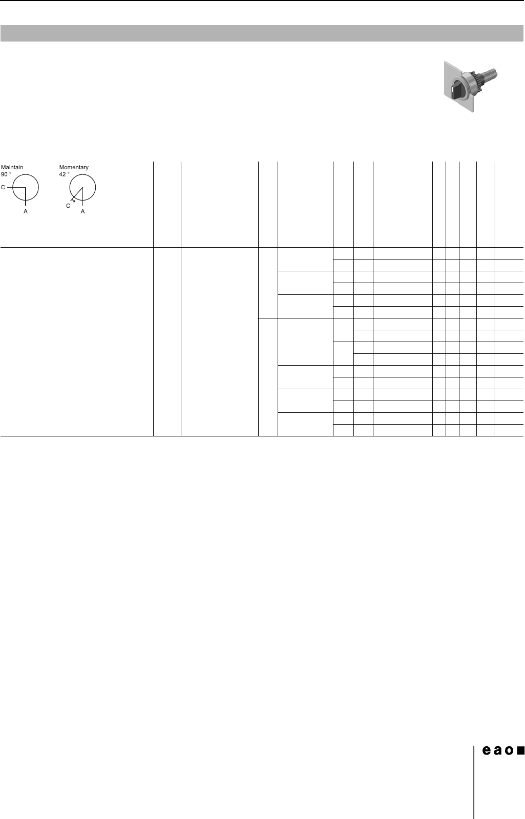
Selector switch actuator 2 positions, flush mounting
0
Front protection
Lever
Switching system
Contacts
Switching action
Terminals
Ø 29 mm
Typ-Nr.
Component layout
Mounting dimensions
Technical drawing
Circuit drawing
e
Selector switch actuator 2 positions,
flush mounting
Position A : Basic position
IP 67 Plastic black short LL 1 NC + 1 NO MA UT 14-522.0360 1 1 34 29 0.025
MUT14-517.0360 1 1 34 22 0.025
2 NC MA UT 14-521.0360 1 1 34 28 0.025
MUT14-516.0360 1 1 34 21 0.025
2 NO MA UT 14-520.0360 1 1 34 30 0.025
MUT14-515.0360 1 1 34 23 0.025
SA 1 NC + 1 NO MA S 14-506.02502 134240.024
S1 14-506.0220 134240.024
MS14-501.02502 134170.024
S1 14-501.0220 134170.024
2 NC + 2 NO MA S 14-507.02502 134250.026
MS14-502.02502 134180.026
3 NC + 3 NO MA S 14-508.02502 134260.028
MS14-503.02502 134190.028
4 NC + 4 NO MA S 14-509.02502 134270.030
MS14-504.02502 134200.030
14
Devices flush mounting
18
06.2007
Continuation see next page
Further information in the Technical Data and Typical Applications
Terminals: S1 = Soldering terminal (also pluggable 2.8 x 0.5 mm)
Mounting dimensions from page 37, Technical drawing from page 38, Circuit drawing from page 48
Buzzer, flush mounting
Front protection
Front cap
Terminals
Ø 35 mm
Typ-Nr.
Mounting dimensions
Technical drawing
Circuit drawing
e
Buzzer, flush mounting
Operation voltage : 24 VDC
IP 40 Aluminium black S1 14-810.910 1 21 1 0.016
Aluminium natural S1 14-810.918 1 21 1 0.016