SONY机开关EAO-Series-14-Full-Data.pdf - 第9页
14 Devices raised mounting 10 06.2007 Essential Accessories: d Front ring page 21 d Marking plate for Mushroom-head cap page 20 d Mushroom-head cap illuminated page 20 d Single-LED page 25 Continuation se e next page Swi…
14
Devices raised mounting
9
06.2007
Essential Accessories:
d Front ring page 21
d Marking plate for Mushroom-head cap page 20
d Mushroom-head cap page 20
Continuation see next page
Switching system: LL = Low level switching element, SA = Snap-action switching element
Contacts: NC = Normally closed, NO = Normally open
Switching action: MA = Maintained action, M = Momentary action
Terminals: UT = Universal terminal, S = Soldering terminal, S1 = Soldering terminal (also pluggable 2.8 x 0.5 mm)
Component layout from page 36, Mounting dimensions from page 37, Technical drawing from page 38, Circuit drawing from page 48
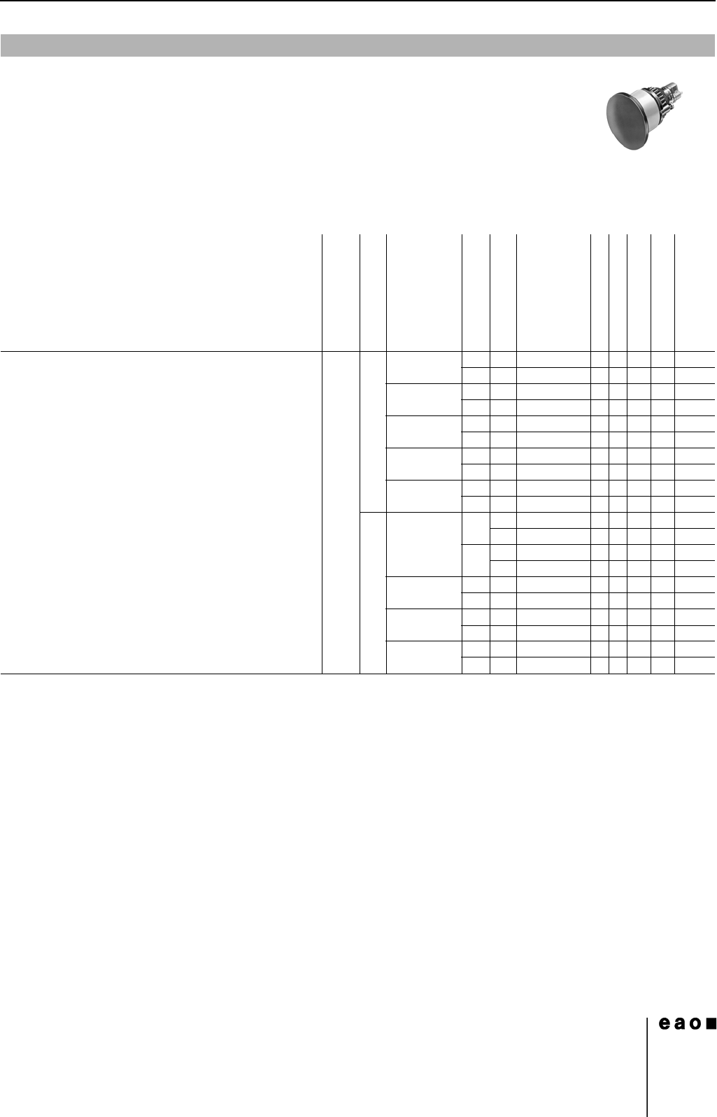
Mushroom-head actuator pushbutton
Front protection
Switching system
Contacts
Switching action
Terminals
Ø 40 mm
Typ-Nr.
Component layout
Mounting dimensions
Technical drawing
Circuit drawing
e
Mushroom-head actuator pushbutton IP 67 LL 1 NC MA UT 14-476.036 1 2 16 12 0.015
MUT14-436.036 1 2 16 39 0.015
1 NC + 1 NO MA UT 14-473.036 1 2 16 15 0.015
MUT14-433.036 1 2 16 42 0.015
1 NO MA UT 14-475.036 1 2 16 14 0.015
MUT14-435.036 1 2 16 41 0.015
2 NC MA UT 14-472.036 1 2 16 13 0.015
MUT14-432.036 1 2 16 40 0.015
2 NO MA UT 14-471.036 1 2 16 16 0.015
MUT14-431.036 1 2 16 43 0.015
SA 1 NC + 1 NO MA S 14-271.0252 223110.013
S1 14-271.022 223110.013
MS14-131.0252 223380.013
S1 14-131.022 223380.013
2 NC + 2 NO MA S 14-272.0252 2 23 8 0.015
MS14-132.0252 223350.015
3 NC + 3 NO MA S 14-273.0252 2 23 5 0.017
MS14-133.0252 223320.017
4 NC + 4 NO MA S 14-274.0252 2 23 4 0.019
MS14-134.0252 223310.019
14
Devices raised mounting
10
06.2007
Essential Accessories:
d Front ring page 21
d Marking plate for Mushroom-head cap page 20
d Mushroom-head cap illuminated page 20
d Single-LED page 25
Continuation see next page
Switching system: LL = Low level switching element, SA = Snap-action switching element
Contacts: NC = Normally closed, NO = Normally open
Diode (1N 4007): - = without, D = Diode
Switching action: MA = Maintained action, M = Momentary action
Terminals: UT = Universal terminal, S = Soldering terminal, S1 = Soldering terminal (also pluggable 2.8 x 0.5 mm)
Component layout from page 36, Mounting dimensions from page 37, Technical drawing from page 38, Circuit drawing from page 48
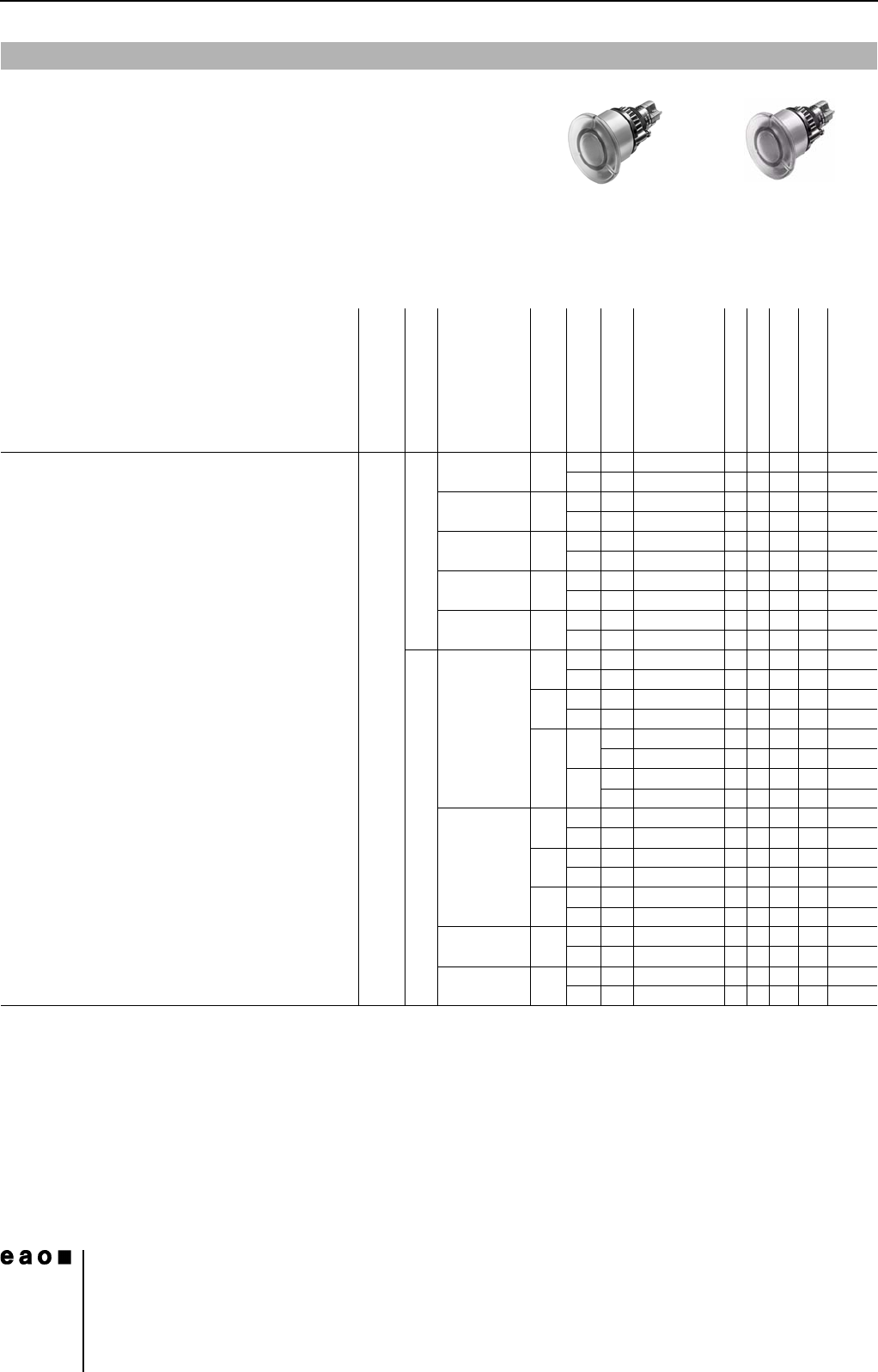
Illuminated mushroom-head actuator pushbutton
Front protection
Switching system
Contacts
Diode (1N 4007)
Switching action
Terminals
Ø 40 mm
Typ-Nr.
Component layout
Mounting dimensions
Technical drawing
Circuit drawing
e
Illuminated mushroom-head actuator pushbutton IP 67 LL 1 NC - MA UT 14-476.036 1216120.015
MUT14-436.036 1216390.015
1 NC + 1 NO - MA UT 14-473.036 1216150.015
MUT14-433.036 1216420.015
1 NO - MA UT 14-475.036 1216140.015
MUT14-435.036 1216410.015
2 NC - MA UT 14-472.036 1216130.015
MUT14-432.036 1216400.015
2 NO - MA UT 14-471.036 1216160.015
MUT14-431.036 1216430.015
SA 1 NC + 1 NO 1 D MA UT 14-747.0292 1 2 25 9 0.014
MUT14-743.0292 1225360.014
2 D MA UT 14-748.0292 1225100.014
MUT14-744.0292 1225370.014
-MAS14-271.0252 2 23 11 0.013
S1 14-271.022 2 23 11 0.013
MS14-131.0252 2 23 38 0.013
S1 14-131.022 2 23 38 0.013
2 NC + 2 NO 1 D MA UT 14-749.0292 1 2 25 6 0.016
MUT14-745.0292 1225330.016
2 D MA UT 14-750.0292 1 2 25 7 0.016
MUT14-746.0292 1225340.016
-MAS14-272.0252 2 23 8 0.015
MS14-132.0252 2 23 35 0.015
3 NC + 3 NO - MA S 14-273.0252 2 23 5 0.017
MS14-133.0252 2 23 32 0.017
4 NC + 4 NO - MA S 14-274.0252 2 23 4 0.019
MS14-134.0252 2 23 31 0.019
14
Devices raised mounting
11
06.2007
Continuation see next page
Keylock switches are supplied with 2 keys.
Other lock numbers on request
Switching system: LL = Low level switching element, SA = Snap-action switching element
Contacts: NC = Normally closed, NO = Normally open
Switching action: MA = Maintained action, M = Momentary action
Terminals: UT = Universal terminal, S = Soldering terminal, S1 = Soldering terminal (also pluggable 2.8 x 0.5 mm)
Component layout from page 36, Mounting dimensions from page 37, Technical drawing from page 38, Circuit drawing from page 48
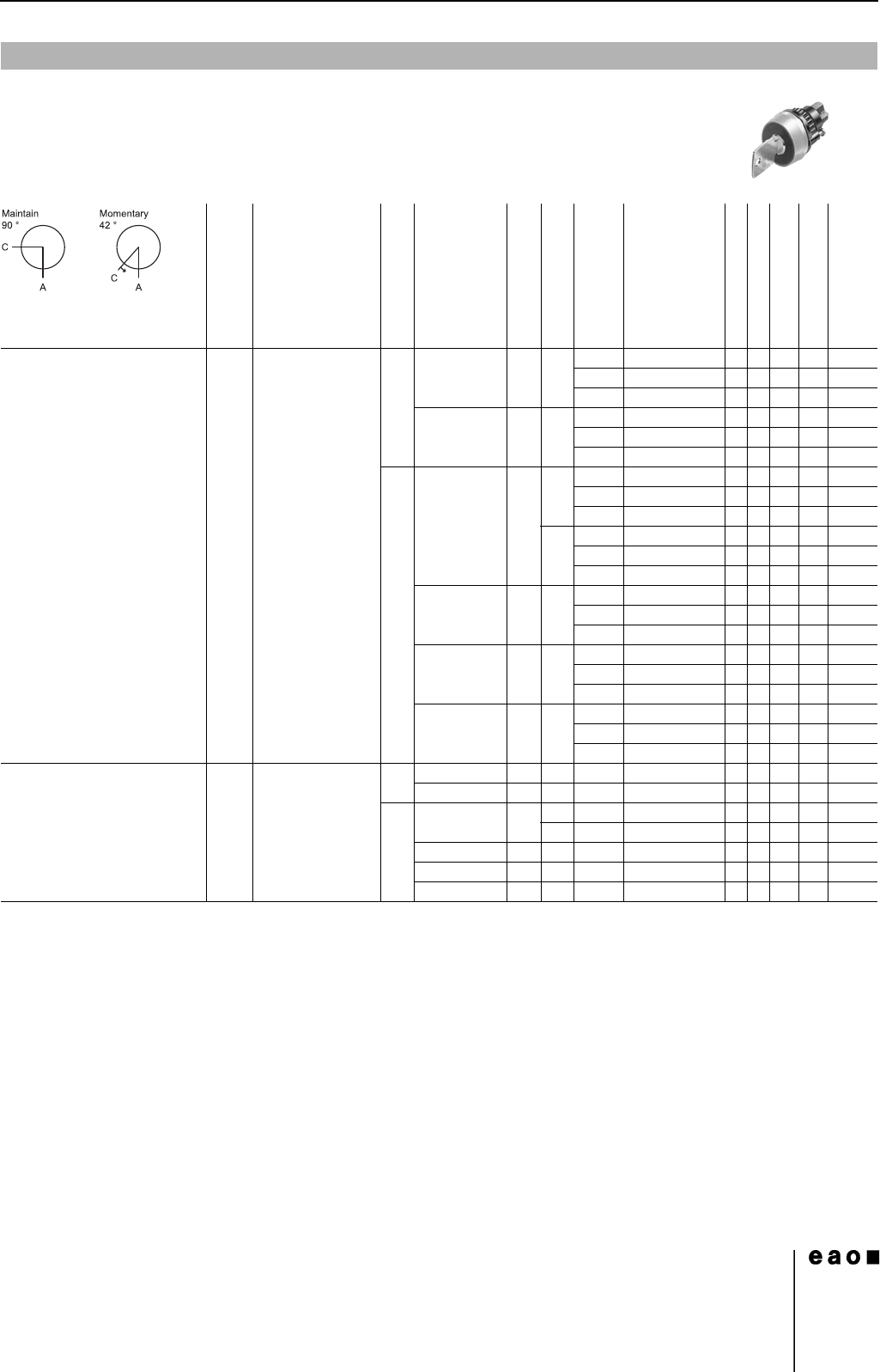
Keylock switch 2 positions
0
Front protection
Front ring
Switching system
Contacts
Switching action
Terminals
Key remove
Ø 29 mm
Typ-Nr.
Component layout
Mounting dimensions
Technical drawing
Circuit drawing
e
Keylock switch 2 positions
Position A : Basic position
Position C : Maintained action
Standard lock 1001,
Front : Plastic black
IP 65 Aluminium natural LL 1 NC + 1 NO MA UT A 14-415.036K 1 4 18 54 0.030
C 14-418.036K 1 4 18 54 0.030
C + A 14-412.036K 1 4 18 54 0.030
2 NO MA UT A 14-414.036K 1 4 18 55 0.030
C 14-417.036K 1 4 18 55 0.030
C + A 14-411.036K 1 4 18 55 0.030
SA 1 NC + 1 NO MA S A 14-235.025K2 427500.029
C 14-335.025K2 427500.029
C + A 14-135.025K2 427500.029
S1 A 14-235.022K 427500.029
C 14-335.022K 427500.029
C + A 14-135.022K 427500.029
2 NC + 2 NO MA S A 14-236.025K2 427510.031
C 14-336.025K2 427510.031
C + A 14-136.025K2 427510.031
3 NC + 3 NO MA S A 14-237.025K2 427520.033
C 14-337.025K2 427520.033
C + A 14-137.025K2 427520.033
4 NC + 4 NO MA S A 14-238.025K2 427530.035
C 14-338.025K2 427530.035
C + A 14-138.025K2 427530.035
Position A : Basic position
Position C : Momentary action
Standard lock 1001
Front : Plastic black
IP 65 Aluminium natural LL 1 NC + 1 NO M UT A 14-438.036K 1 4 18 48 0.030
2 NO M UT A 14-437.036K 1 4 18 49 0.030
SA 1 NC + 1 NO M S A 14-141.025K2 427440.029
S1 A 14-141.022K 427440.029
2 NC + 2 NO M S A 14-142.025K2 427450.031
3 NC + 3 NO M S A 14-143.025K2 427460.033
4 NC + 4 NO M S A 14-144.025K2 427470.035