SONY机开关EAO-Series-14-Full-Data.pdf - 第6页
14 Devices raised mounting 7 06.2007 Essential Accessories: d Lens cap page 20 d Marking cap for Lens cap page 21 d Single-LED page 25 Continuation see ne xt page Diode (1N 4007): D = Diod e, - = without Terminals: UT = …
14
Product Assembly
6
06.2007
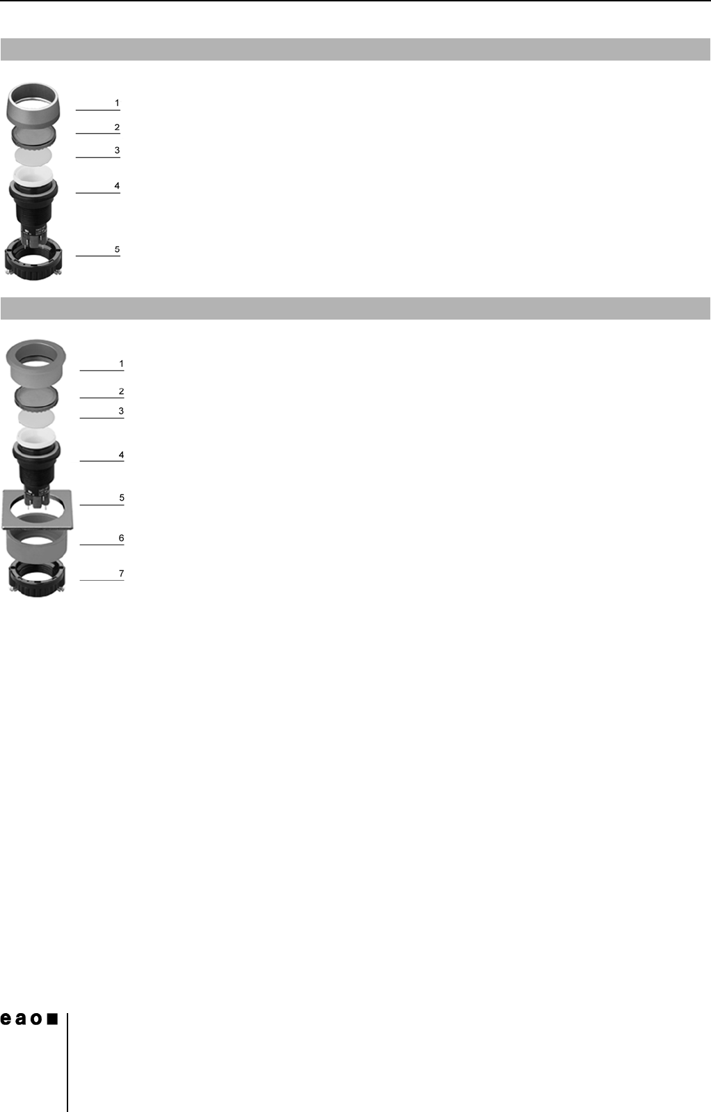
Pushbutton illuminative, raised mounting
0
1 Front ring
2 Lens
3 Marking plate
4 Actuator housing
5 Fixing nut
Pushbutton illuminative, flush mounting
0
1 Front bezel set, flush mounting
2 Lens
3 Marking plate
4 Actuator housing
5 Front panel
6 Pressure ring
7 Fixing nut
14
Devices raised mounting
7
06.2007
Essential Accessories:
d Lens cap page 20
d Marking cap for Lens cap page 21
d Single-LED page 25
Continuation see next page
Diode (1N 4007): D = Diode, - = without
Terminals: UT = Universal terminal, S = Soldering terminal, S1 = Soldering terminal (also pluggable 2.8 x 0.5 mm)
Component layout from page 36, Mounting dimensions from page 37, Technical drawing from page 38, Circuit drawing from page 48
Essential Accessories:
d Front ring page 21
d Lens plastic page 19
d Marking plate for Lens plastic and metal page 20
d Single-LED page 25
Continuation see next page
Terminals: S = Soldering terminal, S1 = Soldering terminal (also pluggable 2.8 x 0.5 mm), UT = Universal terminal
Component layout from page 36, Mounting dimensions from page 37, Technical drawing from page 38, Circuit drawing from page 48
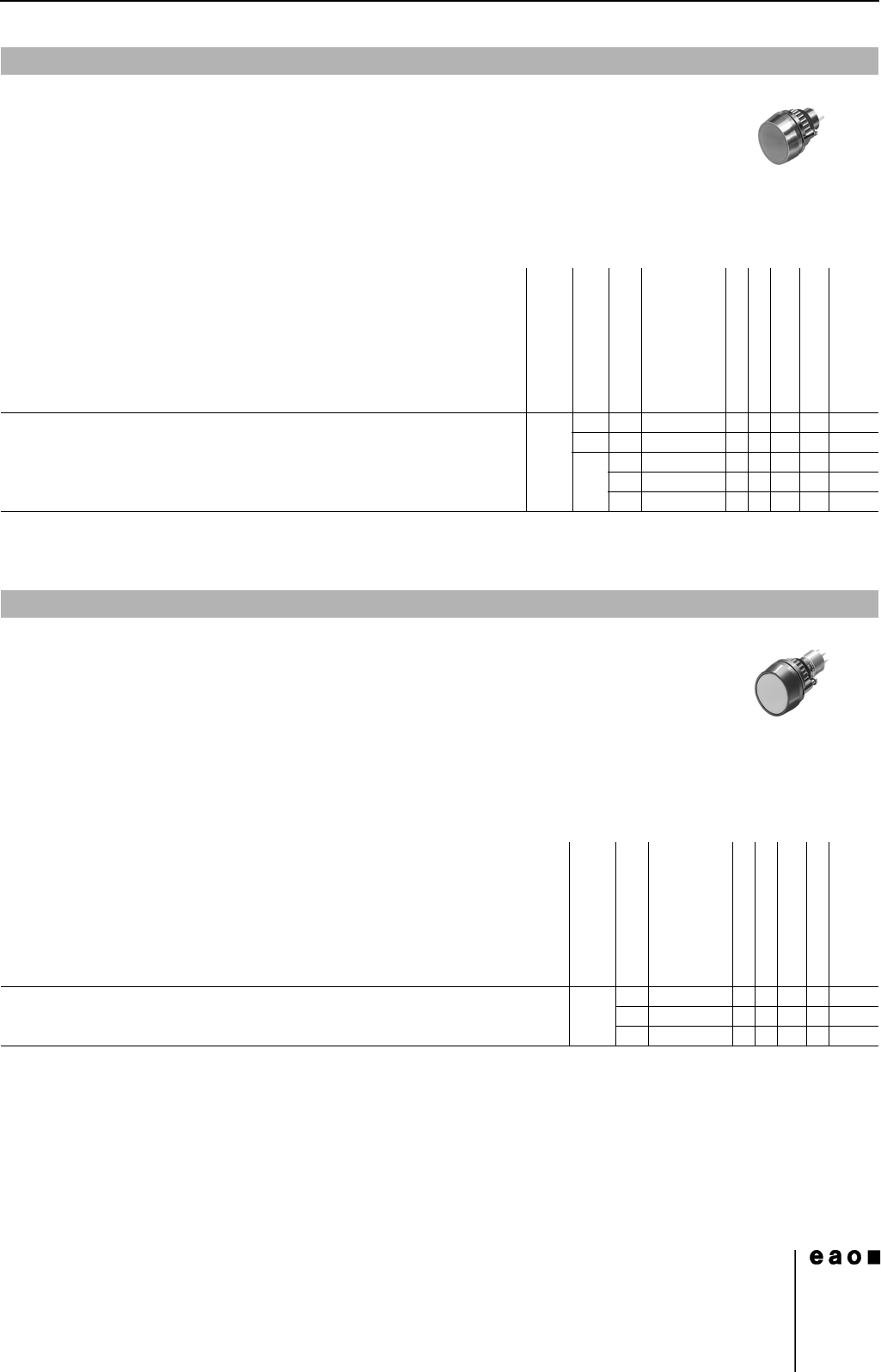
Indicator actuator full face illumination
Front protection
Diode (1N 4007)
Terminals
Ø 29 mm
Typ-Nr.
Component layout
Mounting dimensions
Technical drawing
Circuit drawing
e
Indicator actuator full face illumination IP 67 1 D UT 14-741.006 1 4 17 56 0.011
2 D UT 14-742.006 1 4 17 57 0.011
-S14-030.005 4 22 3 0.010
S1 14-030.002 4 22 3 0.010
UT 14-031.006 14222 0.011
Indicator actuator front illumination
Front protection
Terminals
Ø 29 mm
Typ-Nr.
Component layout
Mounting dimensions
Technical drawing
Circuit drawing
e
Indicator actuator front illumination IP 67 S 14-040.005 4 22 3 0.050
S1 14-040.002 4 22 3 0.050
UT 14-041.006 1 4 22 2 0.050
14
Devices raised mounting
8
06.2007
Essential Accessories:
d Front ring page 21
d Lens plastic page 19
d Marking plate for Lens plastic and metal page 20
d Single-LED page 25
Continuation see next page
Switching system: LL = Low level switching element, SA = Snap-action switching element
Contacts: NC = Normally closed, NO = Normally open
Diode (1N 4007): - = without, D = Diode
Switching action: MA = Maintained action, M = Momentary action
Terminals: UT = Universal terminal, S = Soldering terminal, S1 = Soldering terminal (also pluggable 2.8 x 0.5 mm)
Component layout from page 36, Mounting dimensions from page 37, Technical drawing from page 38, Circuit drawing from page 48
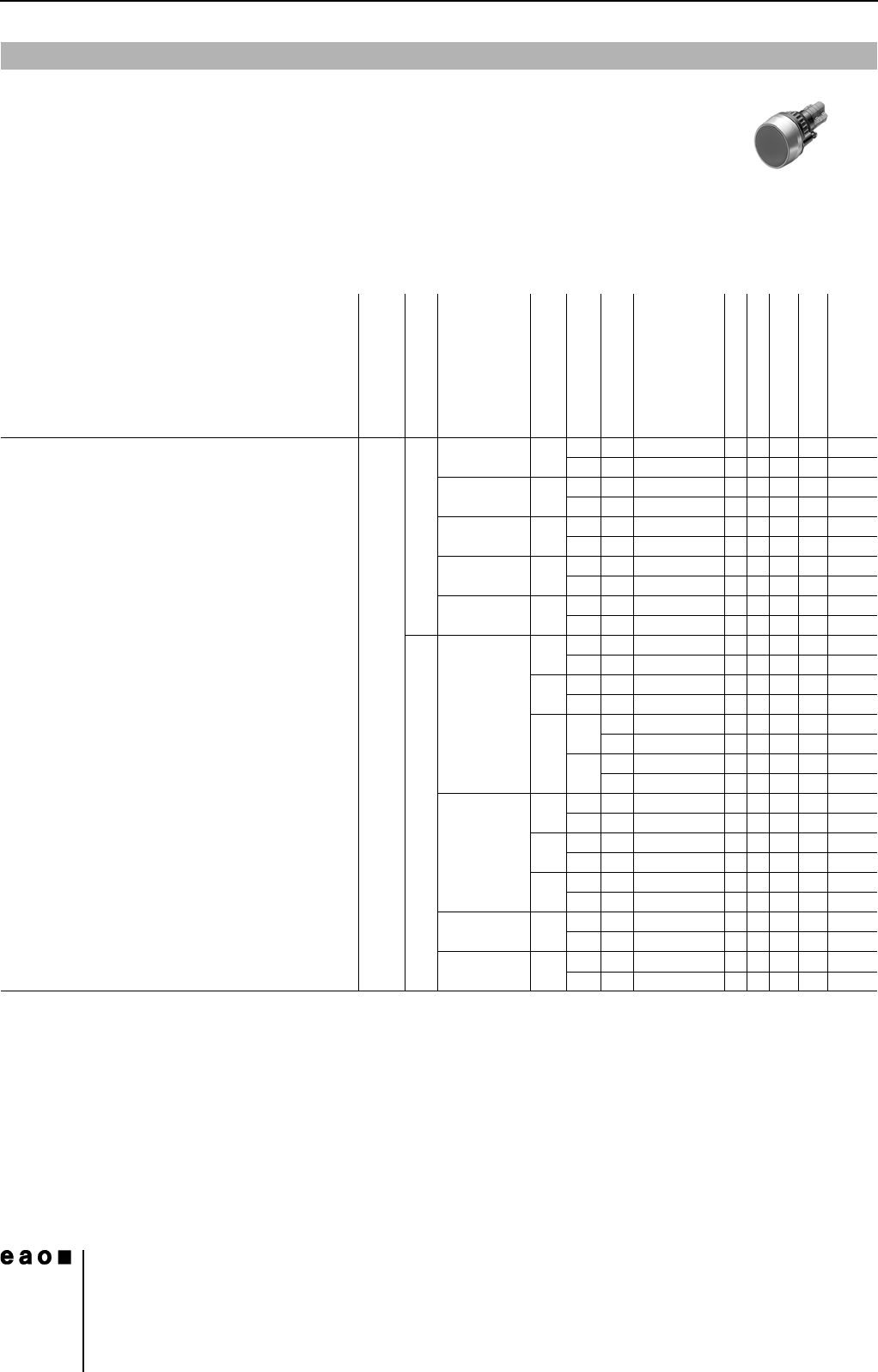
Illuminated actuator pushbutton
Front protection
Switching system
Contacts
Diode (1N 4007)
Switching action
Terminals
Ø 29 mm
Typ-Nr.
Component layout
Mounting dimensions
Technical drawing
Circuit drawing
e
Illuminated actuator pushbutton IP 67 LL 1 NC - MA UT 14-476.036 1417120.015
MUT14-436.036 1417390.015
1 NC + 1 NO - MA UT 14-473.036 1417150.015
MUT14-433.036 1417420.015
1 NO - MA UT 14-475.036 1417140.015
MUT14-435.036 1417410.015
2 NC - MA UT 14-472.036 1417130.015
MUT14-432.036 1417400.015
2 NO - MA UT 14-471.036 1417160.015
MUT14-431.036 1417430.015
SA 1 NC + 1 NO 1 D MA UT 14-747.0292 1 4 26 9 0.014
MUT14-743.0292 1426360.014
2 D MA UT 14-748.0292 1426100.014
MUT14-744.0292 1426370.014
-MAS14-271.0252 4 24 11 0.013
S1 14-271.022 4 24 11 0.013
MS14-131.0252 4 24 38 0.013
S1 14-131.022 4 24 38 0.013
2 NC + 2 NO 1 D MA UT 14-749.0292 1 4 26 6 0.016
MUT14-745.0292 1426330.016
2 D MA UT 14-750.0292 1 4 26 7 0.016
MUT14-746.0292 1426340.016
-MAS14-272.0252 4 24 8 0.015
MS14-132.0252 4 24 35 0.015
3 NC + 3 NO - MA S 14-273.0252 4 24 5 0.017
MS14-133.0252 4 24 32 0.017
4 NC + 4 NO - MA S 14-274.0252 4 24 4 0.019
MS14-134.0252 4 24 31 0.019