SONY机开关EAO-Series-14-Full-Data.pdf - 第13页
14 Devices flush mounting 14 06.2007 Essential Accessories: d Front bezel set, flush mounting page 21 d Lens plastic page 19 d Marking plate for Lens plastic and metal page 20 d Single-LED page 25 Continuation se e next …
14
Devices raised mounting
13
06.2007
Continuation see next page
Further information in the Technical Data and Typical Applications
Terminals: S1 = Soldering terminal (also pluggable 2.8 x 0.5 mm)
Mounting dimensions from page 37, Technical drawing from page 38, Circuit drawing from page 48
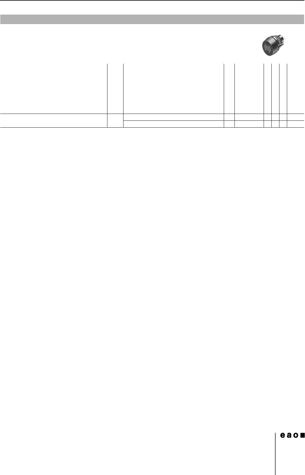
Buzzer
Front protection
Front cap
Terminals
Ø 29 mm
Typ-Nr.
Mounting dimensions
Technical drawing
Circuit drawing
e
Buzzer
Operation voltage 24 VDC
IP 65 Brass chromium-plated S1 14-810.902 4110.016
Plastic black S1 14-810.002 4110.016
14
Devices flush mounting
14
06.2007
Essential Accessories:
d Front bezel set, flush mounting page 21
d Lens plastic page 19
d Marking plate for Lens plastic and metal page 20
d Single-LED page 25
Continuation see next page
Terminals: S = Soldering terminal, S1 = Soldering terminal (also pluggable 2.8 x 0.5 mm), UT = Universal terminal
Component layout from page 36, Mounting dimensions from page 37, Technical drawing from page 38, Circuit drawing from page 48
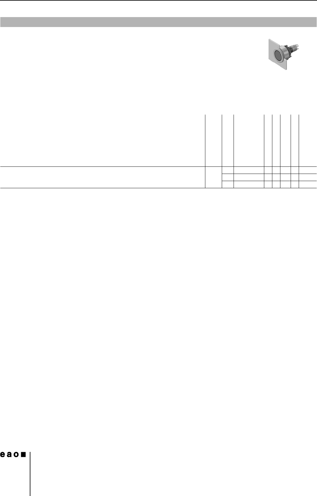
Indicator actuator, flush mounting
Front protection
Terminals
Ø 29 mm
Typ-Nr.
Component layout
Mounting dimensions
Technical drawing
Circuit drawing
e
Indicator actuator, flush mounting IP 67 S 14-040.005 1 30 3 0.050
S1 14-040.002 1 30 3 0.050
UT 14-041.006 1 1 30 3 0.050
14
Devices flush mounting
15
06.2007
Essential Accessories:
d Front bezel set, flush mounting page 21
d Lens plastic page 19
d Marking plate for Lens plastic and metal page 20
d Single-LED page 25
Continuation see next page
Switching system: LL = Low level switching element, SA = Snap-action switching element
Contacts: NC = Normally closed, NO = Normally open
Diode (1N 4007): - = without, D = Diode
Switching action: MA = Maintained action, M = Momentary action
Terminals: UT = Universal terminal, S = Soldering terminal, S1 = Soldering terminal (also pluggable 2.8 x 0.5 mm)
Component layout from page 36, Mounting dimensions from page 37, Technical drawing from page 38, Circuit drawing from page 48
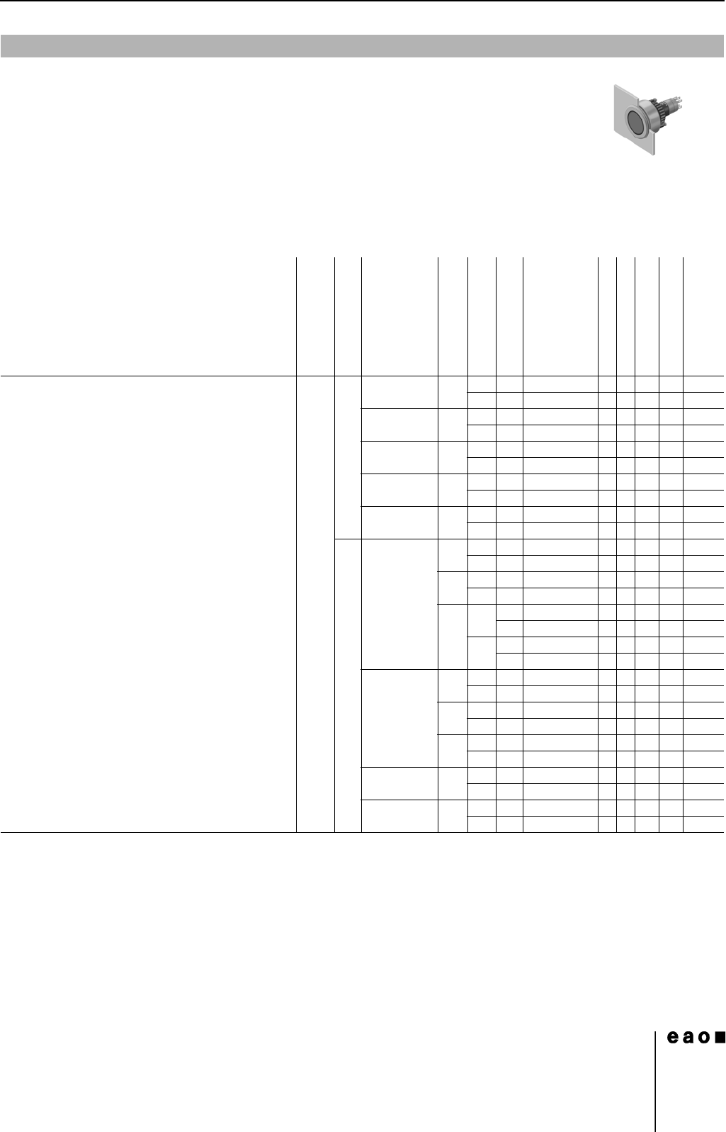
Illuminated pushbutton actuator, flush mounting
Front protection
Switching system
Contacts
Diode (1N 4007)
Switching action
Terminals
Ø 29 mm
Typ-Nr.
Component layout
Mounting dimensions
Technical drawing
Circuit drawing
e
Illuminated pushbutton actuator, flush mounting IP 67 LL 1 NC - MA UT 14-476.036 1 1 32 12 0.015
MUT14-436.036 1 1 32 39 0.015
1 NC + 1 NO - MA UT 14-473.036 1 1 32 15 0.015
MUT14-433.036 1 1 32 42 0.015
1 NO - MA UT 14-475.036 1 1 32 14 0.015
MUT14-435.036 1 1 32 41 0.015
2 NC - MA UT 14-472.036 1 1 32 13 0.015
MUT14-432.036 1 1 32 40 0.015
2 NO - MA UT 14-471.036 1 1 32 16 0.015
MUT14-431.036 1 1 32 43 0.015
SA 1 NC + 1 NO 1 D MA UT 14-747.0292 11319 0.014
MUT14-743.0292 1 1 31 36 0.014
2 D MA UT 14-748.0292 1 1 31 10 0.014
MUT14-744.0292 1 1 31 37 0.014
-MAS14-271.0252 132110.013
S1 14-271.022 132110.013
MS14-131.0252 132380.013
S1 14-131.022 132380.013
2 NC + 2 NO 1 D MA UT 14-749.0292 11316 0.016
MUT14-745.0292 1 1 31 33 0.016
2 D MA UT 14-750.0292 11317 0.016
MUT14-746.0292 1 1 31 34 0.016
-MAS14-272.0252 1 32 8 0.015
MS14-132.0252 132350.015
3 NC + 3 NO - MA S 14-273.0252 1 32 5 0.017
MS14-133.0252 132320.017
4 NC + 4 NO - MA S 14-274.0252 1 32 4 0.019
MS14-134.0252 132310.019