SONY机开关EAO-Series-14-Full-Data.pdf - 第5页
14 Product Assembly 6 06.2007 Pushbutton illuminative , raised mounting 0 1 Front ring 2 Lens 3 Marking plate 4 Actuator housing 5 Fixing nut Pushbutton illuminati ve, flush mounting 0 1 Front bezel set, flush mounting 2…

5
06.2007
14
Description
General notes
The Series 14 illuminated pushbuttons combine the robust actuators of
the Series 04 with choice of either snap-action switching elements with
gold plated silver contacts for one changeover only.
These pushbuttons have an IP 67 proof front and can be immersed to
a depth of one metre.
The range includes pushbuttons, keylock switches and selector
switches.
Anodized aluminium parts can have visible variations due production-
technical reasons.
Mounting
Mounted from the front through either 22.5 mm dia cut out for raised or
30.5 mm dia for flush.
The pushbuttons are secured to the panel by means of a fixing ring/ nut
and prevented from twisting by two srews.
To ensure correct positioning of the pushbuttons we can provide a
positioning insert if required.
The Low Level switching elements with universal terminals allow them
to PCB mounted. These terminals are also suitable for dip soldering. A
plug-in base is available, which when soldered to the board allows the
switch to be easily plugged-in.
Lenses
Lenses of transparent plastic or aluminium are available in various
standard colours.
Marking
For further information about engraving, hot stamping and film inserts
see part Marking.
Illumination
The T5.5 incandescent (filament) lamp (6, 12, 24, 28, 30, 36, 48 V)
ensures perfect illumination of the lenses, which are supplied in various
colours.
T5.5 Single-Chip LED (6, 12, 24, 28, 48 V) are also available in blue,
green, red, white or yellow.
Do not solder the terminals directly, because of the high surface
temperature.
Luminosity and wave length scattering caused by the technology used
in the LED manufacturing processes may lead to visual differences in
our products.
Position indication
The status of a maintained action switch can be determinded by the
position of the lens.
Keylock switch
Single locks (2 positions).
There are 10 different locks with standard numbers 1001 ... 1010. If the
lock number is not specified, we will supply standard number 1001.
Additional lock numbers are available on request.
Two keys are supplied with each keylock switch.
Spare keys for standard locks may be ordered by quoting Typ-Nr.
14-987 (please state the lock number).
Number structure
Nomenclature in accordance with ' CENELEC ENEC AGREEMENT '.
The certification document we dispatch to them on demands.
Specimen order
0
We reserve the right to modify technical data
All dimensions in mm
Product Information
Illuminated pushbutton :
- Illuminiated pushbutton actuator, 29 mm dia.,
snap-action switching element, 1NC + 1 NO,
momentary action, soldering terminal
14-131.0252
Essential accessories :
- Lens plastic red 704.602.2
- Marking plate white translucent 704.609.9
- Front ring aluminium natural 704.600.1
- Single-LED, T5.5, 12 VDC, white 10-2109.1069
14
Product Assembly
6
06.2007
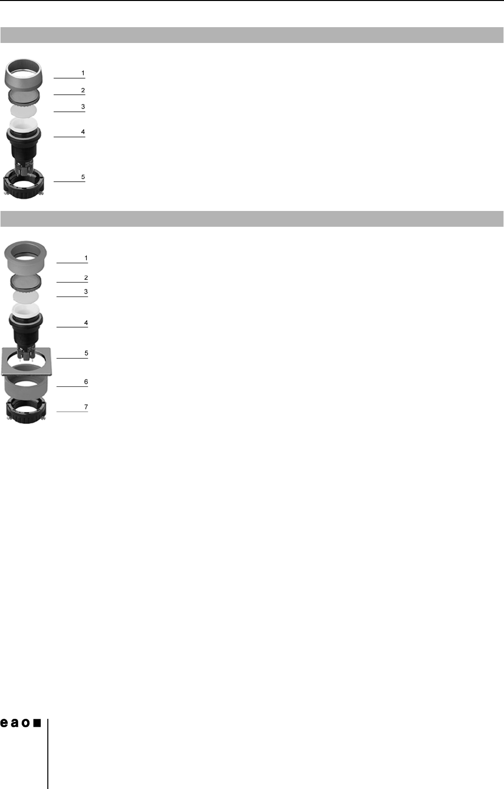
Pushbutton illuminative, raised mounting
0
1 Front ring
2 Lens
3 Marking plate
4 Actuator housing
5 Fixing nut
Pushbutton illuminative, flush mounting
0
1 Front bezel set, flush mounting
2 Lens
3 Marking plate
4 Actuator housing
5 Front panel
6 Pressure ring
7 Fixing nut
14
Devices raised mounting
7
06.2007
Essential Accessories:
d Lens cap page 20
d Marking cap for Lens cap page 21
d Single-LED page 25
Continuation see next page
Diode (1N 4007): D = Diode, - = without
Terminals: UT = Universal terminal, S = Soldering terminal, S1 = Soldering terminal (also pluggable 2.8 x 0.5 mm)
Component layout from page 36, Mounting dimensions from page 37, Technical drawing from page 38, Circuit drawing from page 48
Essential Accessories:
d Front ring page 21
d Lens plastic page 19
d Marking plate for Lens plastic and metal page 20
d Single-LED page 25
Continuation see next page
Terminals: S = Soldering terminal, S1 = Soldering terminal (also pluggable 2.8 x 0.5 mm), UT = Universal terminal
Component layout from page 36, Mounting dimensions from page 37, Technical drawing from page 38, Circuit drawing from page 48
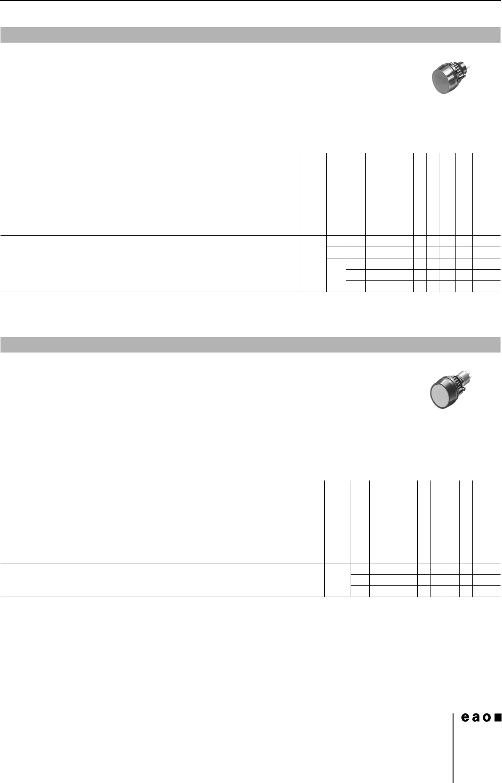
Indicator actuator full face illumination
Front protection
Diode (1N 4007)
Terminals
Ø 29 mm
Typ-Nr.
Component layout
Mounting dimensions
Technical drawing
Circuit drawing
e
Indicator actuator full face illumination IP 67 1 D UT 14-741.006 1 4 17 56 0.011
2 D UT 14-742.006 1 4 17 57 0.011
-S14-030.005 4 22 3 0.010
S1 14-030.002 4 22 3 0.010
UT 14-031.006 14222 0.011
Indicator actuator front illumination
Front protection
Terminals
Ø 29 mm
Typ-Nr.
Component layout
Mounting dimensions
Technical drawing
Circuit drawing
e
Indicator actuator front illumination IP 67 S 14-040.005 4 22 3 0.050
S1 14-040.002 4 22 3 0.050
UT 14-041.006 1 4 22 2 0.050