SONY机开关EAO-Series-14-Full-Data.pdf - 第37页
14 Drawings 38 06.2007 1 Buzzer page 13 2 Blind plug page 23 3 Blind plug page 23 4 Protective cover, raised mountin g page 22 Technica l drawing 2.5...6 28 4.8 20 Ø3 0
14
Drawings
37
06.2007
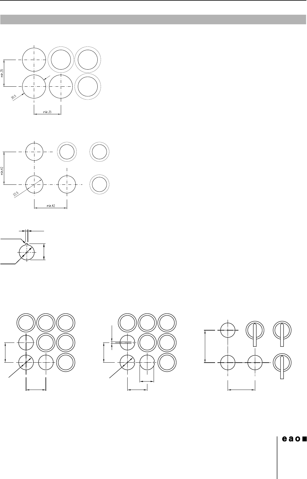
1 Indicator actuator, flush mounting page 14 | Illuminated pushbutton actuator, flush mounting page 15 | Keylock switch actuator
2 positions, flush mounting page 16 | Selector switch actuator 2 positions, flush mounting page 17 | Buzzer, flush mounting page 18 |
Front bezel set, flush mounting page 21
Hole spacing 37 mm min. by using blind plug 704.960.8
2 Mushroom-head actuator pushbutton page 9 | Illuminated mushroom-head actuator pushbutton page 10
3 Positioning insert page 26
4 Indicator actuator full face illumination page 7 | Indicator actuator front illumination page 7 | Illuminated actuator pushbutton page 8 |
Keylock switch 2 positions page 11 | Selector switch 2 positions page 12 | Buzzer page 13
Hole spacing 31 mm min. by using blind plug 704.960.4
Mounting dimensions
+ 0.3
0
+ 0.5
0
R0.8 max.
3.2
+
0.2
0
24.1
+
0.4
0
22.3
+
0.4
0
+0.2
0
min. 30
min. 30
min. 50
min. 30min. 30 min. 42
21.3
0
-
0.1
2.9
+
0.2
0
22.4
+0.2
0
22.5
for devices
Selector switch long lever
for devices
with anti-twist device (rotary)
(recommended for keylock switch)
for devices
without anti-twist device
14
Drawings
38
06.2007
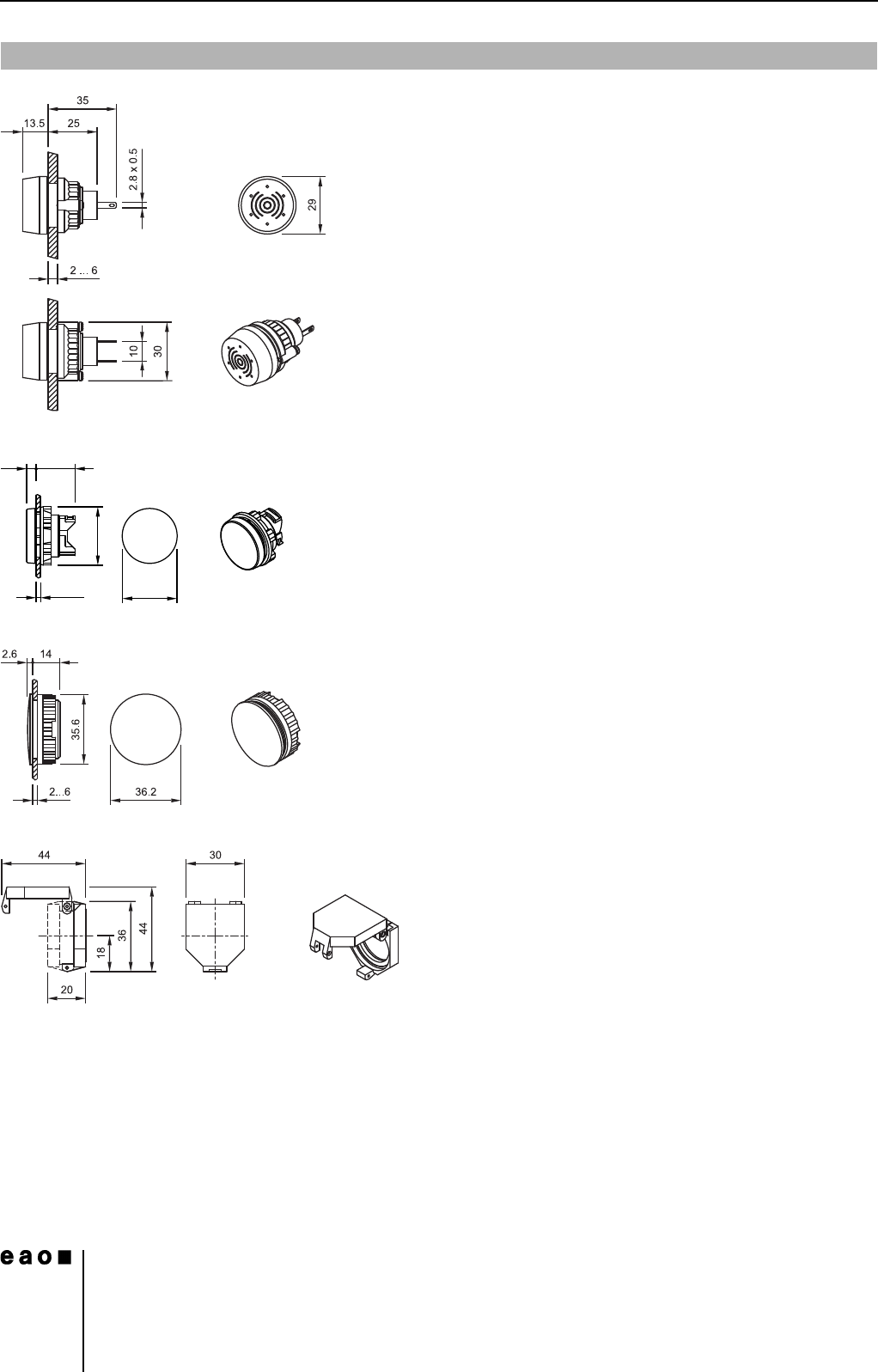
1 Buzzer page 13
2 Blind plug page 23
3 Blind plug page 23
4 Protective cover, raised mounting page 22
Technical drawing
2.5...6
28
4.8 20
Ø30
14
Drawings
39
06.2007
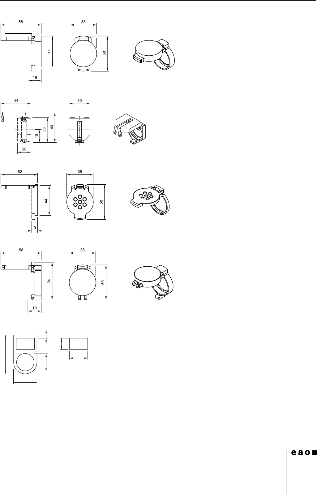
5 Protective cover, flush mounting page 22
6 Protective cover, raised mounting page 22
7 Protective cover, flush mounting page 22
8 Protective cover, flush mounting page 22
9 Legend frame page 22
14.5
50
30
23.5
4
Ø22.5