SONY机开关EAO-Series-14-Full-Data.pdf - 第17页
14 Devices flush mounting 18 06.2007 Continuation se e next page Further information in the Techni cal Da ta and Typical Applications Terminals: S1 = Soldering terminal (also pluggable 2.8 x 0.5 mm) Mounting dimensions f…
14
Devices flush mounting
17
06.2007
Essential Accessories:
d Anti-twist ring, flush mounting page 26
d Front bezel set, flush mounting page 21
Continuation see next page
Switching system: LL = Low level switching element, SA = Snap-action switching element
Contacts: NC = Normally closed, NO = Normally open
Switching action: MA = Maintained action, M = Momentary action
Terminals: UT = Universal terminal, S = Soldering terminal, S1 = Soldering terminal (also pluggable 2.8 x 0.5 mm)
Component layout from page 36, Mounting dimensions from page 37, Technical drawing from page 38, Circuit drawing from page 48
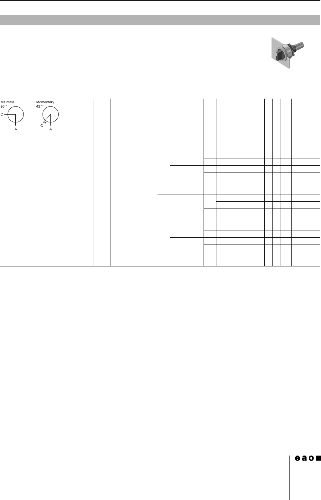
Selector switch actuator 2 positions, flush mounting
0
Front protection
Lever
Switching system
Contacts
Switching action
Terminals
Ø 29 mm
Typ-Nr.
Component layout
Mounting dimensions
Technical drawing
Circuit drawing
e
Selector switch actuator 2 positions,
flush mounting
Position A : Basic position
IP 67 Plastic black short LL 1 NC + 1 NO MA UT 14-522.0360 1 1 34 29 0.025
MUT14-517.0360 1 1 34 22 0.025
2 NC MA UT 14-521.0360 1 1 34 28 0.025
MUT14-516.0360 1 1 34 21 0.025
2 NO MA UT 14-520.0360 1 1 34 30 0.025
MUT14-515.0360 1 1 34 23 0.025
SA 1 NC + 1 NO MA S 14-506.02502 134240.024
S1 14-506.0220 134240.024
MS14-501.02502 134170.024
S1 14-501.0220 134170.024
2 NC + 2 NO MA S 14-507.02502 134250.026
MS14-502.02502 134180.026
3 NC + 3 NO MA S 14-508.02502 134260.028
MS14-503.02502 134190.028
4 NC + 4 NO MA S 14-509.02502 134270.030
MS14-504.02502 134200.030
14
Devices flush mounting
18
06.2007
Continuation see next page
Further information in the Technical Data and Typical Applications
Terminals: S1 = Soldering terminal (also pluggable 2.8 x 0.5 mm)
Mounting dimensions from page 37, Technical drawing from page 38, Circuit drawing from page 48
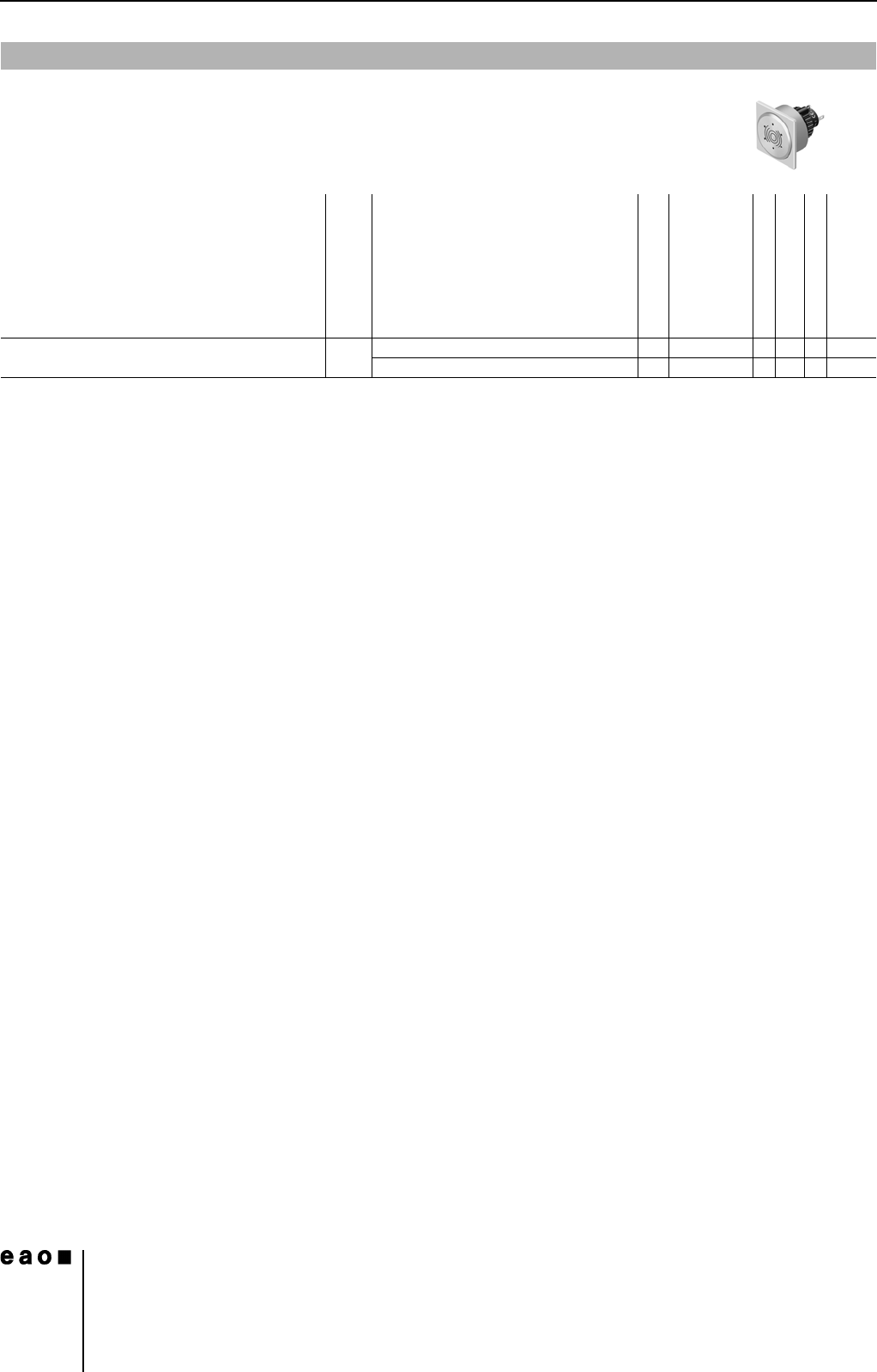
Buzzer, flush mounting
Front protection
Front cap
Terminals
Ø 35 mm
Typ-Nr.
Mounting dimensions
Technical drawing
Circuit drawing
e
Buzzer, flush mounting
Operation voltage : 24 VDC
IP 40 Aluminium black S1 14-810.910 1 21 1 0.016
Aluminium natural S1 14-810.918 1 21 1 0.016
19
06.2007
14
Accessories
To obtain IP 67 use Marking plate Typ-Nr. 704.609.9
Continuation see next page
To obtain IP 67 use Marking plate Typ-Nr. 704.609.9
Continuation see next page
To obtain IP 67 use Marking plate Typ-Nr. 704.609.9
Continuation see next page
To obtain IP 67 use Marking plate Typ-Nr. 704.609.9
Continuation see next page
Front
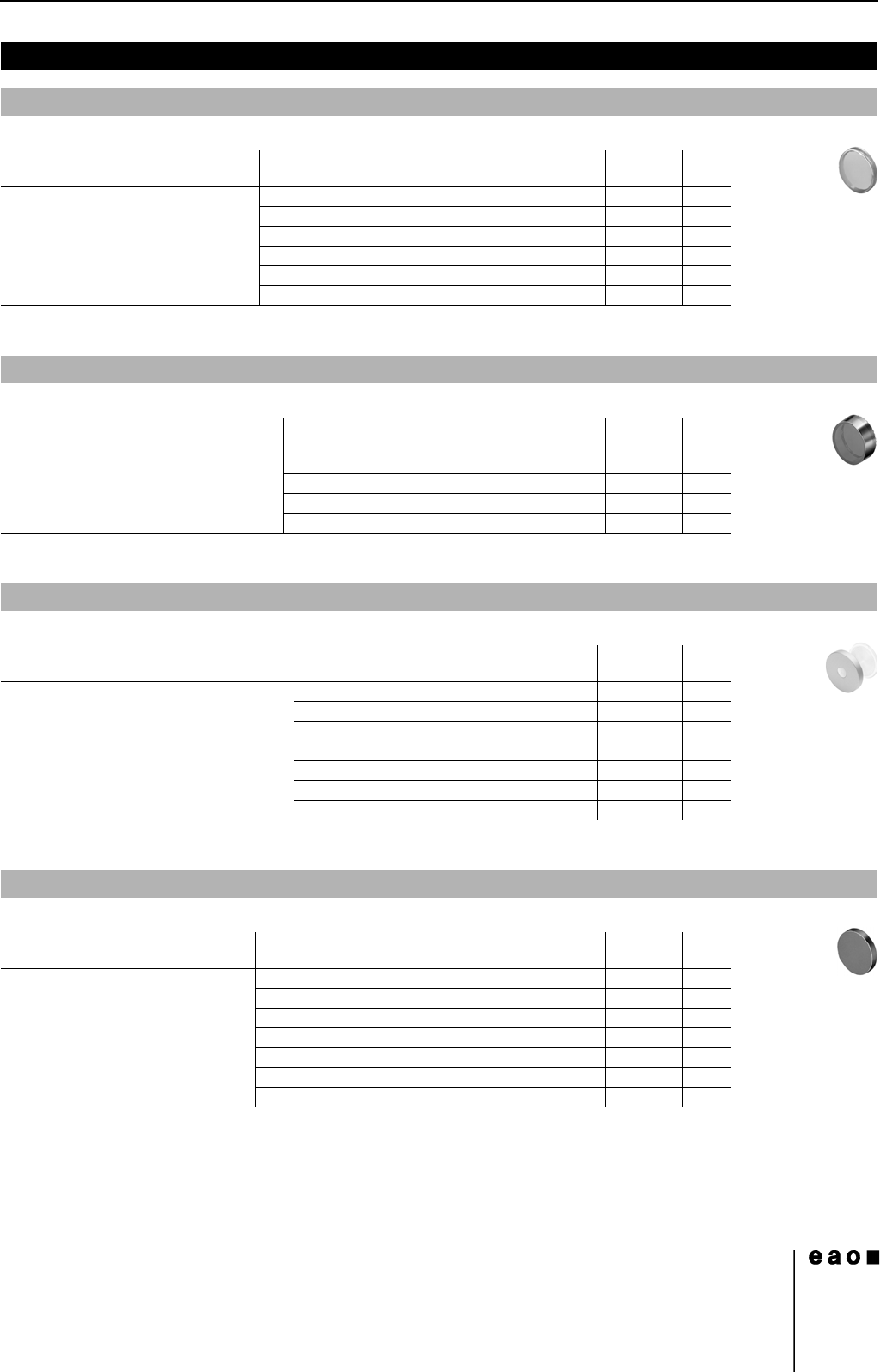
Lens plastic
Lens
Ø 29 mm
Typ-Nr.
e
Lens plastic black opaque flush 704.602.0 0.001
blue transparent flush 704.602.6 0.001
colourless transparent flush 704.602.7 0.001
green transparent flush 704.602.5 0.001
red transparent flush 704.602.2 0.001
yellow transparent flush 704.602.4 0.001
Lens raised, plastic
Lens
Ø 29 mm
Typ-Nr.
e
Lens raised, plastic colourless transparent flush 704.611.7 0.002
green transparent flush 704.611.5 0.002
red transparent flush 704.611.2 0.002
yellow transparent flush 704.611.4 0.002
Lens metal with window
Lens
Ø 29 mm
Typ-Nr.
e
Lens metal with window Aluminium black flush 704.601.01 0.001
Aluminium blue flush 704.601.61 0.001
Aluminium green flush 704.601.51 0.001
Aluminium natural flush 704.601.81 0.001
Aluminium red flush 704.601.21 0.001
Aluminium yellow flush 704.601.41 0.001
Stainless-steel natural flush 704.601.91 0.001
Lens metal
Lens
Ø 29 mm
Typ-Nr.
e
Lens metal Aluminium black flush 704.601.0 0.001
Aluminium blue flush 704.601.6 0.001
Aluminium green flush 704.601.5 0.001
Aluminium natural flush 704.601.8 0.001
Aluminium red flush 704.601.2 0.001
Aluminium yellow flush 704.601.4 0.001
Stainless-steel natural flush 704.601.9 0.001