IPC 7711A.pdf - 第168页
NOTES IPC-771 1A Number: 5.5.4 Revision: Date: 2/98 Subject: Gull Wing Installation P a g e2o f2 Copyright Association Connecting Electronics Industries Provided by IHS under license with IPC Not for Resale No reproducti…
EQUIPMENT NEEDED
Hot air pencil
Hot air tip
Liquid dispensing system
Tweezers
Vacuum pick-up tool
OPTIONAL EQUIPMENT
Manual solder paste dispenser
MATERIALS
Solder paste
Cleaner
Solder paste dispense needles
Tissue/wipe
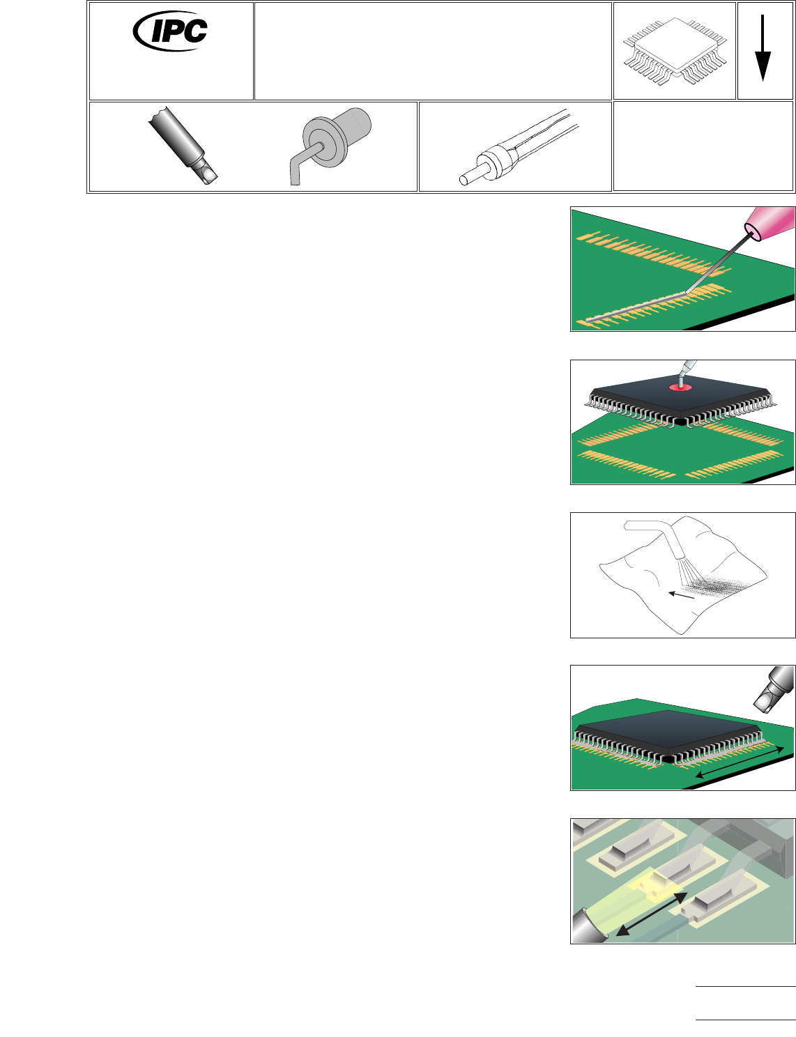
PROCEDURE
1. Install tip into hot air pencil.
2. Set heater temperature of approximately 425°C and change as necessary.
3. Apply a small bead of solder paste along the land pattern using a dispenser. (See
Figure 1.)
4. Position component onto lands using a vacuum pick up tool or tweezers. (See
Figure 2.)
5. Adjust pressure output so hot air scorches a tissue from approximately 0.5 cm
away. (See Figure 3.)
6. Direct hot air over component with tip at a distance of 2.5 cm to pre-dry solder
paste. (See Figure 4.)
7. When pre-drying is observed (paste has dull, flat appearance), move tip closer
(0.5 cm) and heat until complete solder melt is observed. (See Figure 5.)
8. Clean, if required, and inspect.
Figure 1 Apply Solder Paste
Figure 2 Position Component
Figure 3 Adjust Pressure
Figure 4 Pre-dry Paste
Figure 5 Melt Joints
7711A
Rework of
Electronic Assemblies
Revision:
Date: 2/98
Gull Wing Installation
Hot Air Pencil/Solder Paste Method
Number: 5.5.4
Product Class: R, F, W, C
Skill Level: Advanced
Level of Conformance: High
Material in this manual, IPC-7711 Rework of Electronic Assemblies, was voluntarily established by Technical Committees of
IPC. This material is advisory only and its use or adaptation is entirely voluntary. IPC disclaims all liability of any kind as to the
use, application, or adaptation of this material. Users are also wholly responsible for protecting themselves against all claims
or liabilities for patent infringement. Equipment referenced is for the convenience of the user and does not imply endorsement
by IPC.
Page1of2
Copyright Association Connecting Electronics Industries
Provided by IHS under license with IPC
Not for Resale
No reproduction or networking permitted without license from IHS
--``,``,-`-`,,`,,`,`,,`---

NOTES
IPC-7711A
Number: 5.5.4
Revision:
Date: 2/98
Subject: Gull Wing Installation
Page2of2
Copyright Association Connecting Electronics Industries
Provided by IHS under license with IPC
Not for Resale
No reproduction or networking permitted without license from IHS
--``,``,-`-`,,`,,`,`,,`---
EQUIPMENT REQUIRED
Soldering system
Soldering handpiece
Hook tip
MATERIALS
Solder form wire recommended less than 0.4 mm
Flux-cored solder
Flux
NOTES
The type of vision assistance will vary with the pitch of the components to be sol-
dered and should be determined by the needs of each assembly and/or operator.
The amount of flux necessary is minimal.
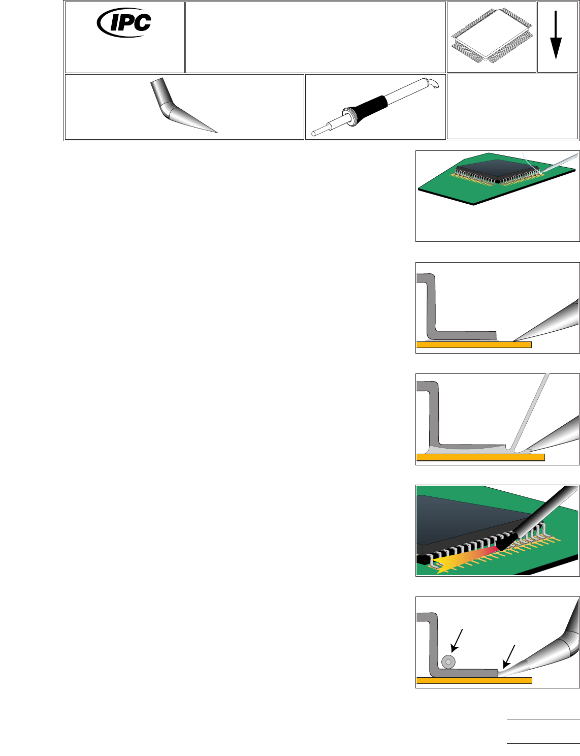
PROCEDURE
1. Install tip into handpiece.
2. Start with tip temperature of approximately 315°C and change as necessary.
3. Begin by applying flux to a corner land, then place a light bump of solder evenly
across the land. This will be the first of two points that will fix the component to
the board. (See Figure 1.)
4. Align the component to the lands. Since one lead will be resting on a solder
bump, do not expect proper coplanarity at this point.
5. When the component is properly aligned, lightly flux the prepped land and the
lead over it and bring a clean tip down to the land, in front of the toe of the lead.
Do not contact the lead – heat only the land. (See Figure 2.)
6. Clean tip with damp sponge.
7. Move to the diagonally opposite corner lead from the one that was just tacked.
Reposition the component if the alignment has wandered, and lightly flux the
lead. Place a lightly tinned tip on the land in front of the lead, allow it to absorb
heat for a moment, then feed solder wire to the land at the gap between the tip
and the lead to create the second fixturing joint (See Figure 3.)
8. Lightly flux the first row of leads to be soldered. (See Figure 4.)
9. Lay the solder wire along the inside of the curve that forms the lead’s heel.
10. Tin the tip lightly to create a solder bridge that will facilitate heat transfer.
11. Skipping the tacked leads, move down the row, placing the tip on each land
consecutively, abutting the toe of lead. When the joint is properly formed, move
to the next lead until the row is completed. (See Figure 5.)
Figure 1 Start at Corners
Figure 2 Heat Only Land
Figure 3 Feed Solder into Gap
Figure 4 Flux Leads
Figure 5 Align Tip Lead
Solder Wire
Solder Bridge
7711A
Rework of
Electronic Assemblies
Revision:
Date: 2/98
Gull Wing Installation
Hook Tip w/Wire Layover
Number: 5.5.5
Product Class: R, F, W, C
Skill Level: Intermediate
Level of Conformance: High
Material in this manual, IPC-7711 Rework of Electronic Assemblies, was voluntarily established by Technical Committees of
IPC. This material is advisory only and its use or adaptation is entirely voluntary. IPC disclaims all liability of any kind as to the
use, application, or adaptation of this material. Users are also wholly responsible for protecting themselves against all claims
or liabilities for patent infringement. Equipment referenced is for the convenience of the user and does not imply endorsement
by IPC.
Page1of2
Copyright Association Connecting Electronics Industries
Provided by IHS under license with IPC
Not for Resale
No reproduction or networking permitted without license from IHS
--``,``,-`-`,,`,,`,`,,`---