IPC 7711A.pdf - 第203页
EQUIPMENT REQUIRED Soldering system Soldering handpiece Chisel tip MATERIALS Flux Flux-cored solder Insulative tubing PROCEDURE 1. Install tip 2. Start with tip temperature of approximately 260°C and change as necessary.…

NOTE
Flux contained in flux-cored solders should be sufficient to clean and solder splices.
If external flux is used, the chance of solder wicking beneath the insulation of
stranded wire is increased.
10. Clean, as required, and inspect.
11. Position insulation sleeve/tubing over the spliced area, apply heat to shrink to a
snug fit over the splice and wire. (See Figure 5.)
IPC-7711A
Number: 8.1.3
Revision:
Date: 2/98
Subject: Hook Splice
Page2of2
Copyright Association Connecting Electronics Industries
Provided by IHS under license with IPC
Not for Resale
No reproduction or networking permitted without license from IHS
--``,``,-`-`,,`,,`,`,,`---
EQUIPMENT REQUIRED
Soldering system
Soldering handpiece
Chisel tip
MATERIALS
Flux
Flux-cored solder
Insulative tubing
PROCEDURE
1. Install tip
2. Start with tip temperature of approximately 260°C and change as necessary.
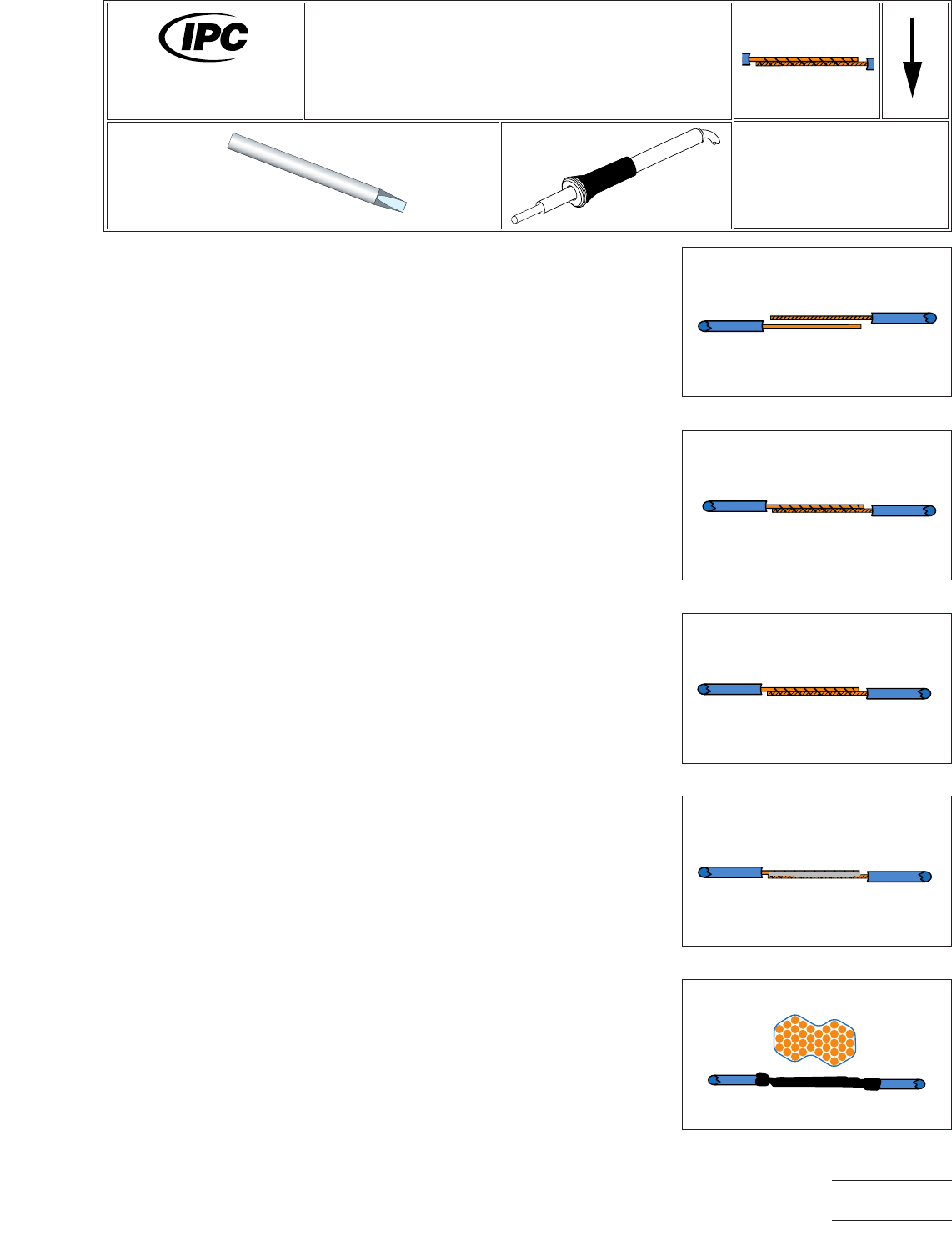
3. Strip the wires. Each wire end should have the same length of insulation removed
so that they appear identical. Each wire end should be stripped a minimum of four
(four) wire diameters (a wire diameter is the outside diameter of the insulator
which covers the conductor). Pre-tin wires in accordance with guidelines in para-
graph 7 in 8.1. (See Figure 1.)
4. Place shrink-sleeving/tubing/wire designators, etc. onto the wire to be spliced
and slide down the wire far enough to avoid interference during soldering. The
inside diameter of the shrink-sleeving should be selected to ensure that a snug,
firm, weather-tight seal will exist after shrinking.
NOTE
Step three (below) requires a single strand of wire, approximately 7.5 cm long, to be
available for wrapping the overlapped wire ends. It is easiest to strip 7.5 cm of wire
by making 3 separate strips (each approximately 2.5 cm long from the spool/reel of
repair wire).
5. If possible, position wires on a flat surface so that the tinned lengths of wire over-
lap and are against each other (like the first two fingers on your hand) and the end
of wire ‘‘a’’ butts against the ends of the insulation of wire ‘‘b.’’ (See Figure 2.) If
identical lengths of insulation were removed, then the end of wire ‘‘b’’ will butt
against the insulation of wire ‘‘a.’’ If it is not possible to position the wires on a flat
surface, then position the wires as described above and secure in position using
hemostats, alligator clips, etc. As a last ditch expedient, the wires can be tack
soldered into the described position. If tack soldered, do not add solder, just heat
the wires sufficiently to achieve a solder bond between the tinned wires.
6. Using a single strand of wire (approximately #30 awg) from a stranded wire (see
Note above), wrap the overlapped wires to achieve sufficient mechanical security
to prevent movement of the overlapped ends during soldering. (See Figure 3.)
Figure 1 Strip and Tin Wires
Figure 2 Line Up Wires
Figure 3 Wrap with #30 Awg Wire
Figure 4 Solder Connection
Figure 5 Cover with Heat-Shrinkable
Tubing
7711A
Rework of
Electronic Assemblies
Revision:
Date: 2/98
Lap Splices
Number: 8.1.4
Product Class: N/A
Skill Level: Intermediate
Level of Conformance: Low
Material in this manual, IPC-7711 Rework of Electronic Assemblies, was voluntarily established by Technical Committees of
IPC. This material is advisory only and its use or adaptation is entirely voluntary. IPC disclaims all liability of any kind as to the
use, application, or adaptation of this material. Users are also wholly responsible for protecting themselves against all claims
or liabilities for patent infringement. Equipment referenced is for the convenience of the user and does not imply endorsement
by IPC.
Page1of2
Copyright Association Connecting Electronics Industries
Provided by IHS under license with IPC
Not for Resale
No reproduction or networking permitted without license from IHS
--``,``,-`-`,,`,,`,`,,`---

NOTE
Do not use magnet or coil wire, due to its insulative enamel coating, to prevent dam-
age to wire during the wrapping procedure.
Use only a single layer of wrapping on the overlapped wires and fold the end of the
wire used for wrapping back down against the wrap surface.
7. Select a soldering iron tip appropriate to soldering the overlap splice. Establish a
heat bridge in the center of the overlapped wires and add sufficient solder to
achieve a complete solder fillet between the full length of the overlapped wires.
The completed solder connection may have a slightly convex fillet for the length
of the connection, as long as the individual wire wraps used to secure the spliced
wires are clearly visible in the solder. (See Figure 4.)
8. Clean the completed connection with the appropriate solvent and visually inspect
in accordance with stated requirements.
9. Position insulative sleeving, shrink-sleeving, or protective tubing over the splice,
assuring that the splice is centered in the length of the sleeving/tubing. Apply heat
to shrink-sleeving as necessary to achieve a tight fit over the splice. Position pro-
tective tubing (if used) over shrink-sleeving and mechanically secure as appropri-
ate. (See Figure 5.)
IPC-7711A
Number: 8.1.4
Revision:
Date: 2/98
Subject: Lap Splice
Page2of2
Copyright Association Connecting Electronics Industries
Provided by IHS under license with IPC
Not for Resale
No reproduction or networking permitted without license from IHS
--``,``,-`-`,,`,,`,`,,`---