IPC 7711A.pdf - 第263页
OUTLINE This method is used on multilayer printed wiring boards or assemblies to disconnect an internal connection at a plated hole. A precision drill press is used with a carbide end mill to make precise cuts at the spo…

check the continuity and inspect the neighboring conductors to make sure that
none of them have been severed or damaged.
If desired complete the following steps
7. Mask the opposite side with Polyimide tape or flexible mask to prevent the
epoxy from flowing out the opposite side.
8. Mix the epoxy.
9. Fill the hole with epoxy up to and flush with the surface. Remove excess epoxy.
(See Figure 3.)
NOTE
A slight overfill of epoxy may be desired to allow for shrinkage when epoxy
cures.
10. Cure the epoxy per the manufacturer’s instructions.
CAUTION
Some components may be sensitive to high temperature.
11. Clean the area.
12. Select an end mill or drill as needed. Insert the cutting tool into the precision drill
press. Mill directly through the center of the cured epoxy. The surface pad
remaining may be used as a target location for accuracy. A microscope should
be used during milling for accuracy. (See Figure 4.)
CAUTION
Be careful not to re-expose the internal layers of the hole when drilling out the
epoxy.
13. Clean the area. Inspect the new hole using a microscope.
EVALUATION
1. Visual and electrical examination as required.
NOTES
IPC-7721A
Number: 4.3.3
Revision:
Date: 2/98
Subject: Deleting Inner Layer Connection At A Plated Hole, Drill
Through Method
Page2of2
Copyright Association Connecting Electronics Industries
Provided by IHS under license with IPC
Not for Resale
No reproduction or networking permitted without license from IHS
--``,``,-`-`,,`,,`,`,,`---
OUTLINE
This method is used on multilayer printed wiring boards or assemblies to disconnect
an internal connection at a plated hole. A precision drill press is used with a carbide
end mill to make precise cuts at the spokes or internal conductors extending from
the hole.
CAUTION
Extreme care must be taken to prevent damage to adjacent conductors. A micro-
scope must be used during milling when extreme accuracy is required.
REFERENCES
2.1 Handling Electronic Assemblies
2.2 Cleaning
2.5 Baking and Preheating
2.6 Epoxy Mixing and Handling
TOOLS AND MATERIALS
Cleaner
Cleaner Wipes
Color Agent
Continuity Meter
End Mills, Carbide
Epoxy
Epoxy Dispensing System
Heat Lamp
Polyimide Tape
Oven
Microscope
Pin Clamps
Precision Drill Press
PROCEDURE
1. Identify the hole that requires rework and clean the area.
2. Mark the coordinates on the board surface and place the printed wiring board
on the base plate of the precision drill press. (See Figure 1.)
3. Select the appropriate size end mill or drill and insert it into the chuck of the
precision drill press. The cutting tool should be approximately 0.010 - 0.025 mm
greater than the width of the spoke or conductor to be cut. (See Table 1 for
Standard End Mill Sizes.) Set speed to high.
CAUTION
Abrasion operations can generate electrostatic charges.
NOTE
End mills are normally single end, two or four flute high grade solid carbide.
Figure 1 Precision drill press with
base plate.
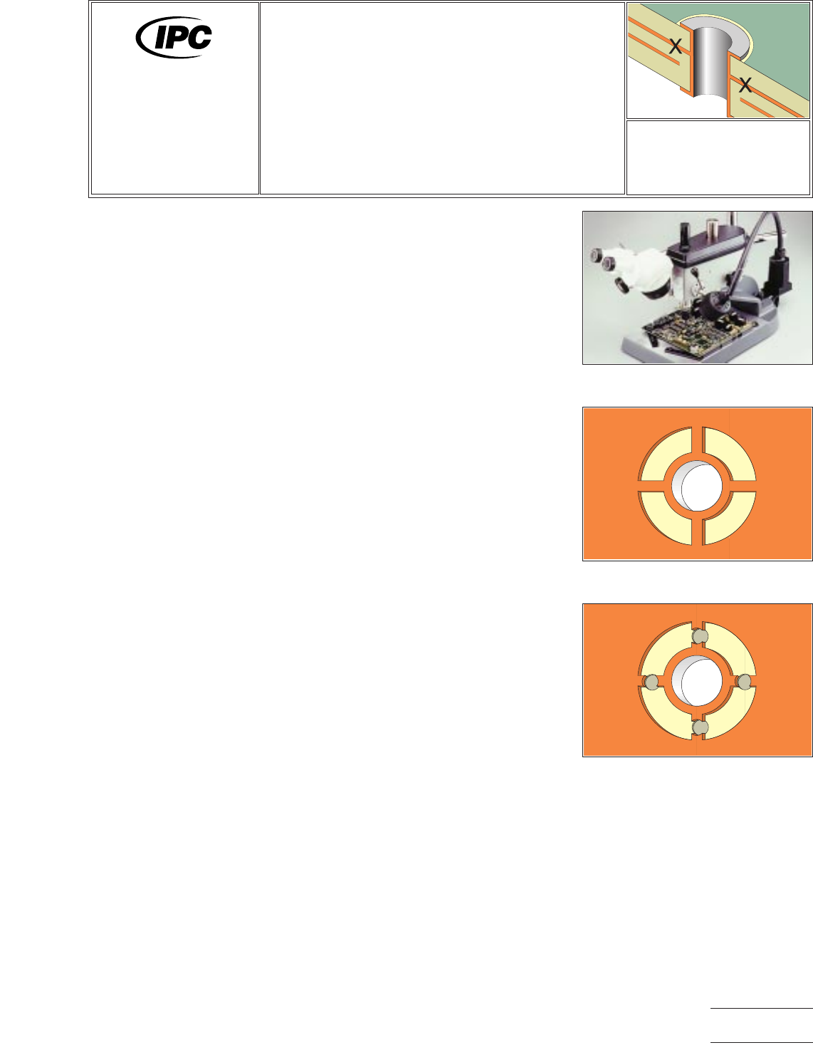
Figure 2 Plated-through hole with
inner layer spoke connections.
Figure 3 Mill adjacent to the plated
hole to sever spoke connections.
7721A
Repair and
Modification of
Printed Boards and
Electronic Assemblies
Revision:
Date: 2/98
Deleting Inner Layer
Connection At A Plated
Hole, Spoke Cut Method
Number: 4.3.4
Product Class: R, F
Skill Level: Advanced
Level of Conformance: High
Material in this manual was voluntarily established by Technical Committees of IPC. This material is advisory only and its use
or adaptation is entirely voluntary. IPC disclaims all liability of any kind as to the use, application, or adaptation of this material.
Users are also wholly responsible for protecting themselves against all claims or liabilities for patent infringement. Equipment
referenced is for the convenience of the user and does not imply endorsement by IPC.
Page1of2
Copyright Association Connecting Electronics Industries
Provided by IHS under license with IPC
Not for Resale
No reproduction or networking permitted without license from IHS
--``,``,-`-`,,`,,`,`,,`---

4. Mill into the printed wiring board surface adjacent to the plated hole. The milled
holes should be aligned directly above the internal spoke connections. Mill down
just deep enough to sever the internal spokes connecting the plated hole to the
internal plane. A microscope must be used for accuracy. Up to 4 milled holes
may be required. Do not drill deeper than needed. (See Figure 3.)
5. Blow away material with air and clean the area.
6. Check continuity to be sure that the internal connection has been deleted. Also
check the continuity and inspect the neighboring conductors to make sure that
none of them have been severed or damaged.
7. Mix the epoxy.
8. Fill the holes with epoxy up to and flush with the surface. Remove excess epoxy.
NOTE
A slight overfill of epoxy may be desired to allow for shrinkage when epoxy
cures.
9. Cure the epoxy per the manufacturer’s instructions.
CAUTION
Some components may be sensitive to high temperature.
10. Clean the area.
EVALUATION
1. Visual and electrical examination as required.
NOTES
Table 1 Standard End Mill Sizes
0.381 mm Diameter
0.635 mm Diameter
0.812 mm Diameter
1.016 mm Diameter
1.143 mm Diameter
1.397 mm Diameter
1.575 mm Diameter
2.362 mm Diameter
3.175 mm Diameter
IPC-7721A
Number: 4.3.4
Revision:
Date: 2/98
Subject: Deleting Inner Layer Connection At A Plated Hole, Spoke
Cut Method
Page2of2
Copyright Association Connecting Electronics Industries
Provided by IHS under license with IPC
Not for Resale
No reproduction or networking permitted without license from IHS
--``,``,-`-`,,`,,`,`,,`---