s25061872.pdf - 第3页
Sensors 2025 , 25 , 1872 3 of 24 to overcome these shortcomings [ 20 – 23 ]. Lu and W ang [ 24 ] built an optimal trajectory planning method based on a B-spline and a WOA to improve the work efficiency of a robotic arm. H…

Sensors 2025, 25, 1872
2 of 24
plan smooth motion trajectories [
5
–
7
]. From the perspective of advanced computational
methods, Xiao et al. [
8
] successfully mitigated the shock and vibration experienced by a
robot during its movement from the starting position to the target position in Cartesian
space, thereby ensuring the accuracy and safety of point-to-point movements. In contrast,
Zhang et al. [
9
] successfully planned two sets of trajectories using polynomial interpolation
in Joint space and verified the model by using SimMechanics. However, owing to the
insufficient robustness of the PID controller against external environmental factors, the sim-
plification of the model significantly affected the accuracy of the experiment. Additionally,
the improved quantum particle swarm optimization algorithm proposed by Luo et al. [
10
]
performed outstandingly in the trajectory planning of the robot joint space, effectively
enhancing the efficiency and accuracy of trajectory planning. Regarding the S-shaped
speed curve, Wu et al. [
11
] investigated how to plan trajectories in Joint space of industrial
robots that satisfy kinematic constraints and have continuous jerk. Nevertheless, trajectory
planning in Joint space requires complex inverse kinematic solutions. Due to joint coupling
effects, trajectories converted to Cartesian space may exhibit distortions or deviations from
the desired path. This constitutes a potential issue for manipulator arms employed in
wafer-handling scenarios.
Trajectory planning curves are vital for motion control strategies. The common types
include linear interpolation, B-spline curves, polynomial curves, T-shaped speed curves,
and S-shaped speed curves. Polynomial interpolation is frequently employed for this
purpose. By selecting the appropriate polynomial order, its adaptability can be flexibly
adjusted to match different numbers of data points and smooth the curve, thus effectively
reducing the vibration and shock of the robotic arm during movement [
12
–
14
]. Although
high-order polynomial interpolation can provide a smoother curve fit, it may lead to the
Runge phenomenon with an excessive number of data points. In addition, they are highly
sensitive to minor data point variations, potentially leading to numerical instability. Fur-
thermore, Cong et al. [
15
] proposed the use of fifth-order Non-uniform B-spline curves in
the trajectory planning and crafted a multi-objective trajectory optimization model employ-
ing the Non-dominated Sorting Genetic Algorithm-II (NSGA2). Regarding the T-shaped
speed curve, Ayazbay et al. [
16
] applied a mini-mum time-impact planning algorithm to
optimize the curve, targeting an enhanced dynamic performance and reduced mechanical
wear. However, this curve lacked smoothness at the endpoints, necessitating additional
processing to ensure the overall continuity and smoothness of the trajectory. In response to
these limitations, researchers have proposed S-shaped speed curves
[17,18]
as trajectory
planning curves, which are distinguished by smooth transitions at the velocity inflection
points. This results in less impact force and noise compared to the T-shaped accelera-
tion and deceleration phases. S-shaped speed curves are commonly used in applications
requiring precise control and minimization of mechanical vibration.
Heuristic algorithms are increasingly employed in trajectory planning and typically
address complex optimization problems when it is difficult to find an exact solution or when
the cost of computing an exact solution is too high. Intelligent algorithms, such as genetic
algorithms (GA), particle swarm optimization (PSO) algorithms, annealing algorithms (SA),
whale optimization algorithms (WOA), and grey wolf optimization (GWO) algorithms
provide novel solutions for addressing intricate trajectory planning problems. They have
the characteristics of flexibility, robustness, and diversity, which can help users find the
global optimal solutions. Among them, the PSO algorithm [
19
], which simulates the social
behavior of bird flocks to achieve optimization, is widely used to optimize the use of robotic
arms owing to its simplicity, ease of implementation, and strong ability for multi-modal
optimization. However, the PSO algorithm cannot avoid problems of parameter sensitivity
and convergence acceleration. Therefore, research teams have improved to varying degrees

Sensors 2025, 25, 1872
3 of 24
to overcome these shortcomings [
20
–
23
]. Lu and Wang [
24
] built an optimal trajectory
planning method based on a B-spline and a WOA to improve the work efficiency of a
robotic arm. However, they did not fully compare the performance differences between the
WOA and other existing algorithms. By combining the back propagation neural network
(BPNN) with the GA, the overall performance of the upper limb rehabilitation robotic arm
trajectory planning was improved to some extent. However, the parameter adjustment
after the combination was very complex and required a large number of experiments and
professional knowledge for correction [
25
]. The SO algorithm excels outstanding in the
realm of optimization owing to its exceptional flexibility and robustness. It is not only easy
to integrate chaos theory and learning mechanisms to bolster search efficiency but also
to maintain efficient exploration ability under poor initial conditions. In addition, it can
rapidly adapt to the changes in dynamic environments and optimize search strategies in
real time, thereby safeguarding the continuity and effectiveness of the optimization process.
Li et al. used a SO algorithm to find optimal paths in dynamic environments. Although its
performance has been improved compared with other intelligent algorithms, the improved
algorithm still requires careful parameter tuning [
26
]. To address the shortcomings of the
SO algorithm, recent literature [
27
,
28
] begun to focus on solving its core mechanism to
raise the overall performance of optimization problems. The ISO has also been gradually
applied to path planning and to solve general constrained optimization problems.
Therefore, considering the shortcomings of the afore-mentioned studies and the main
factors that should be prioritized during the actual operation of the wafer manipulator,
this study proposes an improved control strategy for a manipulator that combines the
single-segment start–stop S-shaped speed of the circular arc transition, an ISO algorithm,
and a time-impact optimization method of trajectory planning. It is worth noting that
it has more advantages in terms of the stability of the control effect or the convergence
ability of the algorithm compared with other types of methods. And it can adapt to
parameter optimization in different scenarios. In summary, the contributions of this study
are as follows.
(1)
In the area of intelligent optimization methods, the following improvements have
been made to the SO algorithm.
•
The Tent Chaotic Map initializes populations, instead of randomly generating
populations with ‘rand’ functions.
•
Dynamic learning factors, integrated with random perturbations, replace static
learning factors.
•
A cosine annealing learning rate scheme is employed for the adaptive updating
of individual positions.
•
The Bayesian method is utilized to optimize thresholds, surpassing the reliance
on empirical thresholds.
(2)
In the area of trajectory planning, the following improvements have been made to the
S-shaped speed curve.
• The interpolated arc transition supplants the abrupt right-angle transition.
•
The continuous single-segment start–stop mechanism supersedes the segmented
start–stop mechanism.
2. Materials and Methods
2.1. The Structure Parameters of the Wafer-Handling Robotic Arms
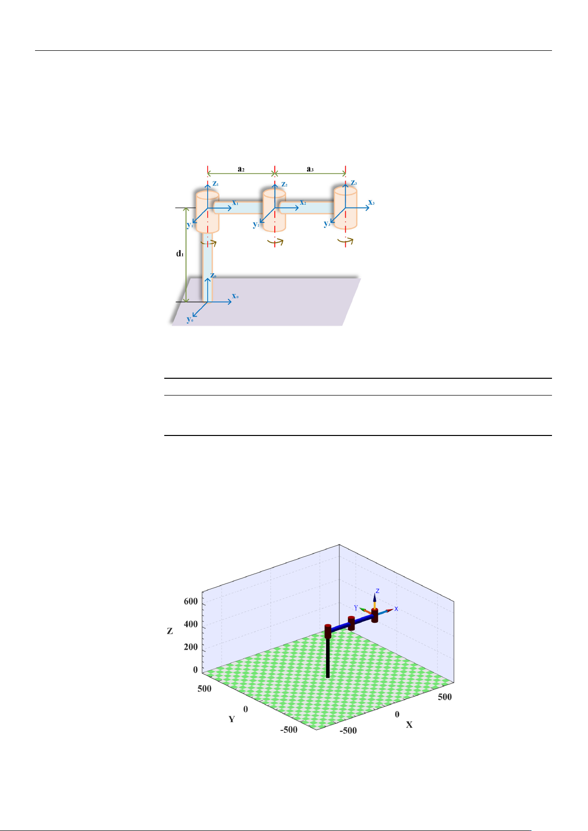
Assuming that the task requirements can be realized in a plane, the system model
is simplified when the robotic arm transports the wafer, as shown in Figure 1. Before
planning the trajectory, it is necessary to establish the link coordinate system correctly. In
Sensors 2025, 25, 1872
4 of 24
general, the points along the Z
i
axis are aligned with the i-th joint axis. Furthermore, the
points along the X
i
axis are aligned with a common vertical line. In addition, the Y
i
axis is
oriented according to the right-hand rule. In this study, the parameters of the linkage rods
are expressed using the improved Denavit–Hartenberg (DH) method. The parameters of
each joint and link are obtained using the link coordinate system as a reference, as shown
in Table 1.
Sensors2025,25,xFORPEERREVIEW 4 of 25
2.MaterialsandMethods
2.1.TheStructureParametersoftheWafer‐HandlingRoboticArms
Assumingthatthetaskrequirementscanberealizedinaplane,thesystemmodel
issimplifiedwhentheroboticarmtransportsthewafer,asshowninFigure1.Beforeplan‐
ningthetrajectory,itisnecessarytoestablishthelink
coordinatesystemcorrectly.Ingen‐
eral,thepointsalongtheZ
iaxisarealignedwiththei‐thjointaxis.Furthermore,thepoints
alongtheX
i axisarealignedwitha comm on vert ical line. In addition, the Yiaxisis
orientedaccordingtotheright‐handrule.Inthisstudy,theparametersofthelinkagerods
areexpressedusingtheimprovedDe navit–Hartenberg(DH) method.Theparameters
of each joint and linkare obtained using the link coordinatesystem as a reference, as
showninTable1.
Figure1.Simplifiedmodelofthewafer‐handlingroboticarm.
Table1.Linkageparametersofthe3Rroboticarm.
Linki ai/mmαi/(°) di/mmθi(/°) Rangeofθi/(°)
1 0 0 400 0 −120–120
2 0 238.4 0 0 −120–120
3 0 238.4 0 0 −120–120
Tofacilitatethevisualanalysisofthesubsequenttrajectoryplanningandverifythe
correctnessofthesimplifiedmodel,thisstudyutilizestheMATLABrobottoolboxdevel‐
opedbyPeterCorke.Itisapowerfulroboticsimulationandanalysistoolthatprovidesa
rangeofcapabilitiesformodeling,simulating,controlling,and
visualizingrobots.Aro‐
boticarmconsistentwiththesimplifiedmodelissuccessfullyconstructedontheinterface
byfollowingthebuildinginstructionsintheMATLABrobottoolbox,asshowninFigure
2.
Figure 1. Simplified model of the wafer-handling robotic arm.
Table 1. Linkage parameters of the 3R robotic arm.
Link
i
a
i
/mm α
i
/(
◦
) d
i
/mm θ
i
(/
◦
) Range of θ
i
/(
◦
)
1 0 0 400 0 −120–120
2 0 238.4 0 0 −120–120
3 0 238.4 0 0 −120–120
To facilitate the visual analysis of the subsequent trajectory planning and verify the
correctness of the simplified model, this study utilizes the MATLAB robot toolbox devel-
oped by Peter Corke. It is a powerful robotic simulation and analysis tool that provides a
range of capabilities for modeling, simulating, controlling, and visualizing robots. A robotic
arm consistent with the simplified model is successfully constructed on the interface by
following the building instructions in the MATLAB robot toolbox, as shown in Figure 2.
Sensors2025,25,xFORPEERREVIEW 5 of 25
Figure2.Wafer−handlingroboticarminMATLAB.
2.2.TheMathematicalModelofMultipleObjectiveFunction
Inrecentyears,theoptimizationoftime,energy,impact,andotherindicatorshas
beenshowntoimprovetheoperationalefficiencyandmotionperformanceofroboticarms
inthefieldofrobottrajectoryplanning[29–31].Inthepreprocessingstageoftrajectory
optimization
analysis,expected traject ori es asinputpara meters needtobepr edefined
and generated. Therefore, this study will build the expected trajectory through the
MATLABplatform,andthespecificimplementationprocesswillbeelaboratedinthefol‐
lowing sections. Considering the production background and opt imization effect, a
multi‐segmentpoint‐to
‐poi nt trajectoryinCartesianspaceisadoptedtoachievemulti‐
objectiveoptimizationoftimeandimpact.Inthefollowingsection,wewillsystematically
analyzethemathematicalmodelanditsoptimizationprocess.
Initially,thedesiredtrajectoryoftheroboticarmisdiscretizedintomultipleinterpo‐
lationpointswithintheCartesianspace.
Theseinterpolationpointsareselectedatregular
timeintervalsalongthedesired trajectory,therebya ccurate lycapturingtheposit i ona l
informationofthetrajectoryatdifferenttimeinstances.Subsequently,theCartesiancoor‐
dinatesoftheseinterpolationpointsarestoredinthejointcontroller.Byemployingthe
inversekinematicsequations,theCartesiancoordinates
oftheinterpolationpointscanbe
furthertransformedintothecorrespondingjointanglesinthejointspace.However,the
inversekinematicsequationstypicallyyieldtwodistinctsolutions.Therefore,itisneces‐
sarytoimposegeometricconstraintswithinthecodetoselecttheuniquesolutionthat
conformstothedesiredtrajectory.
Oncetheuniquesolutionisobtained,itissubstituted
intothe robot’s forward kinemati cs model to deri ve theCartesian coordinatesofthe
desiredtraject ory.Ulti mately,bycombin i ngthe trajectory fu nctionwiththeCartesian
coordinatesoftheinterpolationpoints,thedesiredtrajectoryispreciselyreconstructed.It
isassumedthatthetimeat
whichthemanipulatorreacheseachinterpolationpointist
i
.
Thetimeintervalbetweenadjacentinterpolationpoints ish
i
=t
i+1
−t
i
,whereiistheindex
oftheinterpolationpo ints(i=0,1,…n).Theti meint ervaltakeninthecodeofthispaper
is0.002s,thatis,theselectionbasis ofinterpolationpoints.Atthesa metime,through
thepreliminaryanalysis,itisclearlyobservedthat
thereisaninversecorrelationbetween
timeandimpact.Whenthetimeoftheroboticarmincreases,theimpactdecreases.
Therefore,itisimpossibletosimultaneouslyobtaintheminimu mvalues.Thus, con‐
sideringtheconstraintsofthegeometricjointsoftheroboticarm,velocity,accelera‐
tion,andjerk,theprimarygoal
ofthisstudyistoachieveanoptimalbalancebetweentime
andimpact.Therefore,a Paretooptimalmethodisadoptedinthisstudytoachieve the
tradeoffbetweenoptimizationobjectives.ThetimefunctionisgivenbyEquation(1).
Figure 2. Wafer−handling robotic arm in MATLAB.