s25061872.pdf - 第5页
Sensors 2025 , 25 , 1872 5 of 24 2.2. The Mathematical Model of Multiple Objective Function In recent years, the optimization of time, energy , impact, and other indicators has been shown to impr ove the operational effic…
Sensors 2025, 25, 1872
4 of 24
general, the points along the Z
i
axis are aligned with the i-th joint axis. Furthermore, the
points along the X
i
axis are aligned with a common vertical line. In addition, the Y
i
axis is
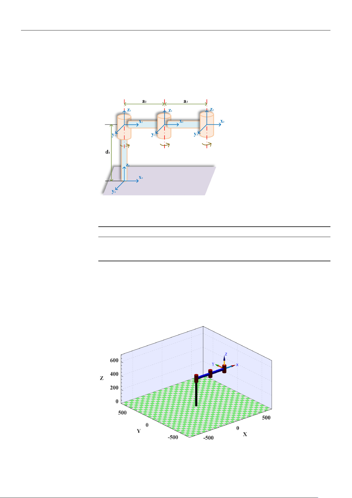
oriented according to the right-hand rule. In this study, the parameters of the linkage rods
are expressed using the improved Denavit–Hartenberg (DH) method. The parameters of
each joint and link are obtained using the link coordinate system as a reference, as shown
in Table 1.
Sensors2025,25,xFORPEERREVIEW 4 of 25
2.MaterialsandMethods
2.1.TheStructureParametersoftheWafer‐HandlingRoboticArms
Assumingthatthetaskrequirementscanberealizedinaplane,thesystemmodel
issimplifiedwhentheroboticarmtransportsthewafer,asshowninFigure1.Beforeplan‐
ningthetrajectory,itisnecessarytoestablishthelink
coordinatesystemcorrectly.Ingen‐
eral,thepointsalongtheZ
iaxisarealignedwiththei‐thjointaxis.Furthermore,thepoints
alongtheX
i axisarealignedwitha comm on vert ical line. In addition, the Yiaxisis
orientedaccordingtotheright‐handrule.Inthisstudy,theparametersofthelinkagerods
areexpressedusingtheimprovedDe navit–Hartenberg(DH) method.Theparameters
of each joint and linkare obtained using the link coordinatesystem as a reference, as
showninTable1.
Figure1.Simplifiedmodelofthewafer‐handlingroboticarm.
Table1.Linkageparametersofthe3Rroboticarm.
Linki ai/mmαi/(°) di/mmθi(/°) Rangeofθi/(°)
1 0 0 400 0 −120–120
2 0 238.4 0 0 −120–120
3 0 238.4 0 0 −120–120
Tofacilitatethevisualanalysisofthesubsequenttrajectoryplanningandverifythe
correctnessofthesimplifiedmodel,thisstudyutilizestheMATLABrobottoolboxdevel‐
opedbyPeterCorke.Itisapowerfulroboticsimulationandanalysistoolthatprovidesa
rangeofcapabilitiesformodeling,simulating,controlling,and
visualizingrobots.Aro‐
boticarmconsistentwiththesimplifiedmodelissuccessfullyconstructedontheinterface
byfollowingthebuildinginstructionsintheMATLABrobottoolbox,asshowninFigure
2.
Figure 1. Simplified model of the wafer-handling robotic arm.
Table 1. Linkage parameters of the 3R robotic arm.
Link
i
a
i
/mm α
i
/(
◦
) d
i
/mm θ
i
(/
◦
) Range of θ
i
/(
◦
)
1 0 0 400 0 −120–120
2 0 238.4 0 0 −120–120
3 0 238.4 0 0 −120–120
To facilitate the visual analysis of the subsequent trajectory planning and verify the
correctness of the simplified model, this study utilizes the MATLAB robot toolbox devel-
oped by Peter Corke. It is a powerful robotic simulation and analysis tool that provides a
range of capabilities for modeling, simulating, controlling, and visualizing robots. A robotic
arm consistent with the simplified model is successfully constructed on the interface by
following the building instructions in the MATLAB robot toolbox, as shown in Figure 2.
Sensors2025,25,xFORPEERREVIEW 5 of 25
Figure2.Wafer−handlingroboticarminMATLAB.
2.2.TheMathematicalModelofMultipleObjectiveFunction
Inrecentyears,theoptimizationoftime,energy,impact,andotherindicatorshas
beenshowntoimprovetheoperationalefficiencyandmotionperformanceofroboticarms
inthefieldofrobottrajectoryplanning[29–31].Inthepreprocessingstageoftrajectory
optimization
analysis,expected traject ori es asinputpara meters needtobepr edefined
and generated. Therefore, this study will build the expected trajectory through the
MATLABplatform,andthespecificimplementationprocesswillbeelaboratedinthefol‐
lowing sections. Considering the production background and opt imization effect, a
multi‐segmentpoint‐to
‐poi nt trajectoryinCartesianspaceisadoptedtoachievemulti‐
objectiveoptimizationoftimeandimpact.Inthefollowingsection,wewillsystematically
analyzethemathematicalmodelanditsoptimizationprocess.
Initially,thedesiredtrajectoryoftheroboticarmisdiscretizedintomultipleinterpo‐
lationpointswithintheCartesianspace.
Theseinterpolationpointsareselectedatregular
timeintervalsalongthedesired trajectory,therebya ccurate lycapturingtheposit i ona l
informationofthetrajectoryatdifferenttimeinstances.Subsequently,theCartesiancoor‐
dinatesoftheseinterpolationpointsarestoredinthejointcontroller.Byemployingthe
inversekinematicsequations,theCartesiancoordinates
oftheinterpolationpointscanbe
furthertransformedintothecorrespondingjointanglesinthejointspace.However,the
inversekinematicsequationstypicallyyieldtwodistinctsolutions.Therefore,itisneces‐
sarytoimposegeometricconstraintswithinthecodetoselecttheuniquesolutionthat
conformstothedesiredtrajectory.
Oncetheuniquesolutionisobtained,itissubstituted
intothe robot’s forward kinemati cs model to deri ve theCartesian coordinatesofthe
desiredtraject ory.Ulti mately,bycombin i ngthe trajectory fu nctionwiththeCartesian
coordinatesoftheinterpolationpoints,thedesiredtrajectoryispreciselyreconstructed.It
isassumedthatthetimeat
whichthemanipulatorreacheseachinterpolationpointist
i
.
Thetimeintervalbetweenadjacentinterpolationpoints ish
i
=t
i+1
−t
i
,whereiistheindex
oftheinterpolationpo ints(i=0,1,…n).Theti meint ervaltakeninthecodeofthispaper
is0.002s,thatis,theselectionbasis ofinterpolationpoints.Atthesa metime,through
thepreliminaryanalysis,itisclearlyobservedthat
thereisaninversecorrelationbetween
timeandimpact.Whenthetimeoftheroboticarmincreases,theimpactdecreases.
Therefore,itisimpossibletosimultaneouslyobtaintheminimu mvalues.Thus, con‐
sideringtheconstraintsofthegeometricjointsoftheroboticarm,velocity,accelera‐
tion,andjerk,theprimarygoal
ofthisstudyistoachieveanoptimalbalancebetweentime
andimpact.Therefore,a Paretooptimalmethodisadoptedinthisstudytoachieve the
tradeoffbetweenoptimizationobjectives.ThetimefunctionisgivenbyEquation(1).
Figure 2. Wafer−handling robotic arm in MATLAB.

Sensors 2025, 25, 1872
5 of 24
2.2. The Mathematical Model of Multiple Objective Function
In recent years, the optimization of time, energy, impact, and other indicators has been
shown to improve the operational efficiency and motion performance of robotic arms in the
field of robot trajectory planning [
29
–
31
]. In the preprocessing stage of trajectory optimiza-
tion analysis, expected trajectories as input parameters need to be predefined and generated.
Therefore, this study will build the expected trajectory through the MATLAB platform, and
the specific implementation process will be elaborated in the following sections. Consider-
ing the production background and optimization effect, a multi-segment point-to-point
trajectory in Cartesian space is adopted to achieve multi-objective optimization of time and
impact. In the following section, we will systematically analyze the mathematical model
and its optimization process.
Initially, the desired trajectory of the robotic arm is discretized into multiple interpola-
tion points within the Cartesian space. These interpolation points are selected at regular
time intervals along the desired trajectory, thereby accurately capturing the positional infor-
mation of the trajectory at different time instances. Subsequently, the Cartesian coordinates
of these interpolation points are stored in the joint controller. By employing the inverse
kinematics equations, the Cartesian coordinates of the interpolation points can be further
transformed into the corresponding joint angles in the joint space. However, the inverse
kinematics equations typically yield two distinct solutions. Therefore, it is necessary to
impose geometric constraints within the code to select the unique solution that conforms to
the desired trajectory. Once the unique solution is obtained, it is substituted into the robot’s
forward kinematics model to derive the Cartesian coordinates of the desired trajectory.
Ultimately, by combining the trajectory function with the Cartesian coordinates of the
interpolation points, the desired trajectory is precisely reconstructed. It is assumed that
the time at which the manipulator reaches each interpolation point is t
i
. The time interval
between adjacent interpolation points is h
i
= t
i+
1
−
t
i
, where i is the index of the interpola-
tion points (i = 0, 1, . . . n). The time interval taken in the code of this paper is 0.002 s, that
is, the selection basis of interpolation points. At the same time, through the preliminary
analysis, it is clearly observed that there is an inverse correlation between time and impact.
When the time of the robotic arm increases, the impact decreases. Therefore, it is impossible
to simultaneously obtain the minimum values. Thus, considering the constraints of the
geometric joints of the robotic arm, velocity, acceleration, and jerk, the primary goal of
this study is to achieve an optimal balance between time and impact. Therefore, a Pareto
optimal method is adopted in this study to achieve the tradeoff between optimization
objectives. The time function is given by Equation (1). Because the impact quantity can
not be directly measured, it is quantified by the acceleration, as shown in Equation (2).
The constraints are expressed in Equation (3). The multi-objective optimization function is
shown in Equation (4).
minF
1
=
n
∑
i=0
h
i
(1)
minF
2
=
n
∑
i=0
s
R
t
i
0
j
2
i
dt
t
i
(2)
|
θ
i
|
≤ θ
max
|
v
i
|
≤ v
max
|
a
i
|
≤ a
max
|
j
i
|
≤ j
max
(3)
minF = w
1
·
|
F
1
− F
1min
|
+ w
2
·
|
F
2
− F
2min
|
(4)
Sensors 2025, 25, 1872
6 of 24
where F
1
, F
1min
, and w
1
are the objective function, minimum value, and weight value of
time, respectively. F
2
, F
2min
, and w
2
are the objective function, minimum value, and weight
of impact, respectively. h
i
is the time interval between the i-th and i + 1-th interpolation
point. t
i
and j
i
denote the time node and jerk value of the i-th interpolation point.
θ
max
,
v
max
, a
max
, and j
max
are the maximum rotational angle, speed, acceleration, and jerk of the
joint of the manipulator arm, respectively.
2.3. The Construction of Trajectory Planning
2.3.1. The Explanation of S-Shaped Speed Curve
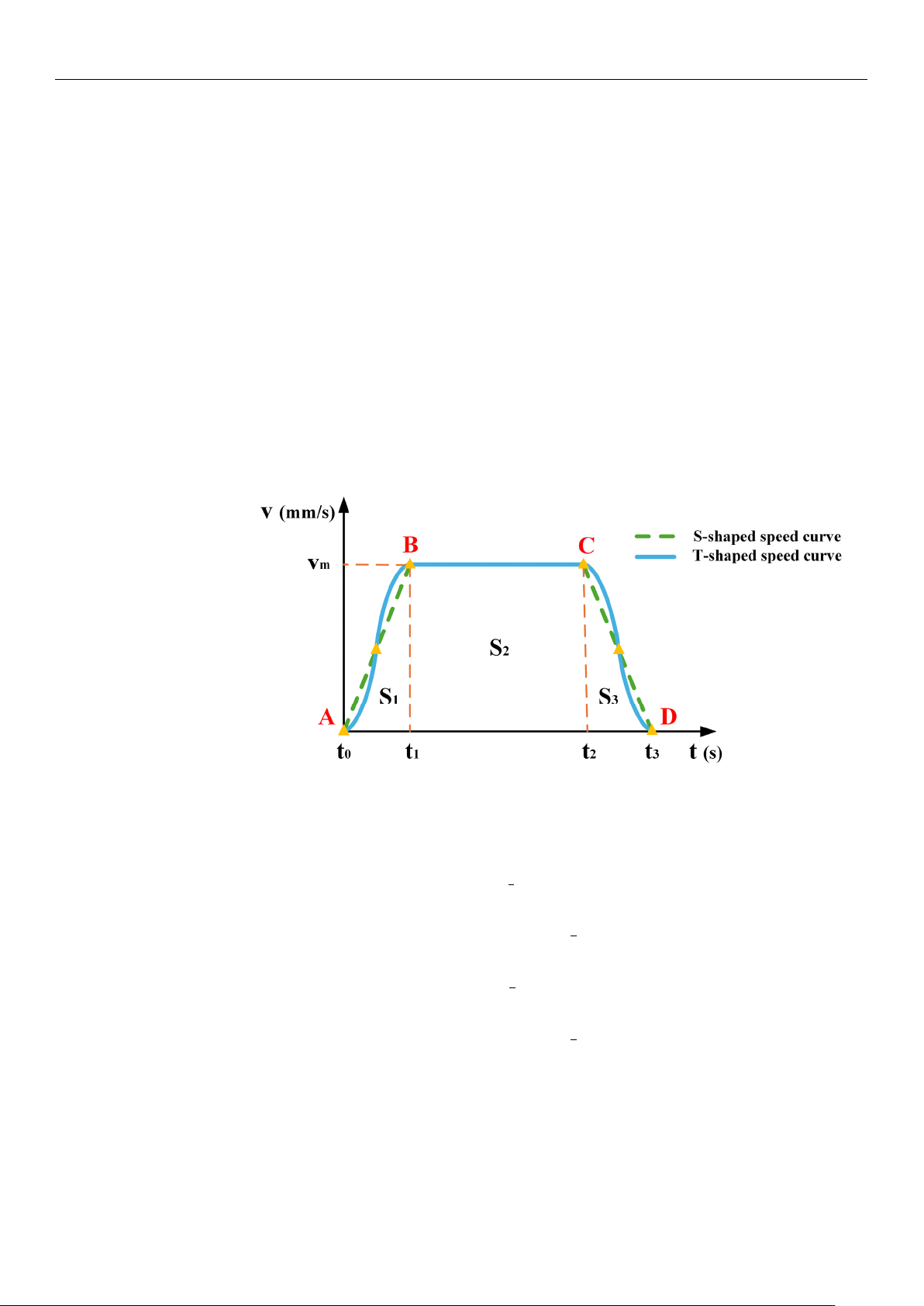
The T-shaped speed curve is a widely used method for robotic arm control. Because
of its simplicity and ease of control, it is extremely common in industrial applications.
As shown in Figure 3, this curve may produce large impacts and vibrations at points
A, B, C, and D, potentially causing the wafer to break. By contrast, the S-shaped speed
curve uses nonlinear adjustments to increase and decrease the velocity, making the motion
process smoother and effectively solving the discontinuity problem of the acceleration of
the
T-shaped
speed curve. Therefore, the S-shaped speed curve is more suitable in scenarios
requiring higher operational stability.
Sensors2025,25,xFORPEERREVIEW 7 of 25
localtimeperiodofpartk,whichreferstothedifferencefromthestartingpointofthe
currentpart,calledtimezero,tothetimepointofthecurrentpart.Theequationused
τ
k = tk−tk−1(k=1,2,…7). vk ( k=1,2,…6)representsthefinalspeed ofpart kandvs.
repres entsthei nitialspeed.a
maxisthemaximumacceleration.jmaxisthemaximumaccel‐
eration.
Figure3.CorrelationchartbetweentheT‐shapedandS‐shapedspeedcurves.
2.3.2.TheImprovementoftheS‐ShapedSpeedCurve
Trajectoryplanningisacrucialstepintheroboticmotioncontrol.Whenthewafer‐
handlingroboticarmisinoperation,itfrequentlyencountersturningpointswherethe
directionofmovementrequiresalteration.Theseturningpointsoftenserveasasourceof
abrupt
jerkchanges.Toalleviatethisproblem,anS‐shapedspeedcurveadopts acircular
arctransitionstrategytoguaranteeasmoothtrajectorytransition.Thisstrategynotonly
mitigates the impact and vibrationinduced by therobotic arm but also contributes to
shorteningtheexecutiontimeofthemotiontrajectory.Prior
toconstructingtheS‐shaped
speedcurve,itisimperativetodeterminethekeyinterpolationpointsofthetrajectoryin
Cartesianspace,asindicatedinTable2.Simultaneously,theprincipal motionparameters
mustbesetaspresentedinTable3.v_p
0,v_p1,andv_p2arethevelocitiesoftheinitial
point,thecirculararctransitionsection,andtheterminalpoint,respectively.v
max,amax,and
jmaxdenotethemaximumvelocity,themaximumacceleration,andthemaximumrateof
changeintheaccelerationofanendeffectorinCartesianspace,respectively.ristheradius
ofthecirculararctransitionattheinflectionpoint.
Table2.SegmentationpointsinCartesianspace.
StartingPoint IntermediatePoint EndingPoint
(400,0,400) (200,0,400) (200,200,400)
Table3.ThemainmotionparametersoftheS‐shapedspeedcurve.
v_p0
(mm/s)
v_p
1
(mm/s)
v_p
2
(mm/s)
v
max
(mm/s)
a
max
(mm/s
2
)
j
max
(mm/s
3
)
r
(mm)
0 100 0 100 100 100 30
ThetrajectorycurveshowninFigure4.canbegeneratedby applyingtheparameters
listedin Table 3. to the S‐shaped speedcurve model. In thisfigure, the black lines
represent the direct path without a circular transition, whereas the blue lines show a
smoothpathwitha circulartra nsiti on.
Itisno te wort hythattheradiusofthecircular
Figure 3. Correlation chart between the T-shaped and S-shaped speed curves.
The S-shaped speed curve partitions the entire motion process into seven distinct
phases. Equation (5) describes the motion characteristics at different stages.
v(t) =
v
s
+
1
2
j
max
τ
2
1
0 ≤ t ≤ t
1
v
1
+ a
max
τ
2
t
1
≤ t ≤ t
2
v
2
+ a
max
τ
3
−
1
2
j
max
τ
2
3
t
2
≤ t ≤ t
3
v
3
t
3
≤ t ≤ t
4
v
4
−
1
2
j
max
τ
2
5
t
4
≤ t ≤ t
5
v
5
− a
max
τ
6
t
5
≤ t ≤ t
6
v
6
− a
max
τ
7
+
1
2
j
max
τ
2
7
t
6
≤ t ≤ t
7
(5)
where t
k
(k = 0, 1, . . . 7) represents the transition point time of part k, which indicates the specific
point in time at which each stage begins or ends.
τ
k
(k = 0, 1, .. . 7) represents the local time
period of part k, which refers to the difference from the starting point of the current part, called
time zero, to the time point of the current part. The equation used
τ
k
= t
k
− t
k−
1
(k = 1, 2, .. . 7).
v
k
(k = 1, 2, . . . 6) represents the final speed of part k and vs. represents the initial speed. a
max
is
the maximum acceleration. j
max
is the maximum acceleration.