PR8111、PR8112_user_manual_eng_20191015H.pdf - 第13页
1.2 Names and Functions of Parts 10 1.2 Names and Function s of Part s Front Panel Handle POWE R switch (p. 19) Turns t he power on and off. :Power OFF :Power ON Power LED Lights up when th e instrumen t is being supplie…
1.1 Product Overview and Features
9
1
The PR8111 and PR8112 are compact, lightweight, highly portable pen recorders. You can select
from two power sources (AC adapter or dry-cell batteries) according to where the instrument is
being used, assuring your ability to record data immediately and easily with unparalleled reliability,
wherever you are.
Overview Chapter 1
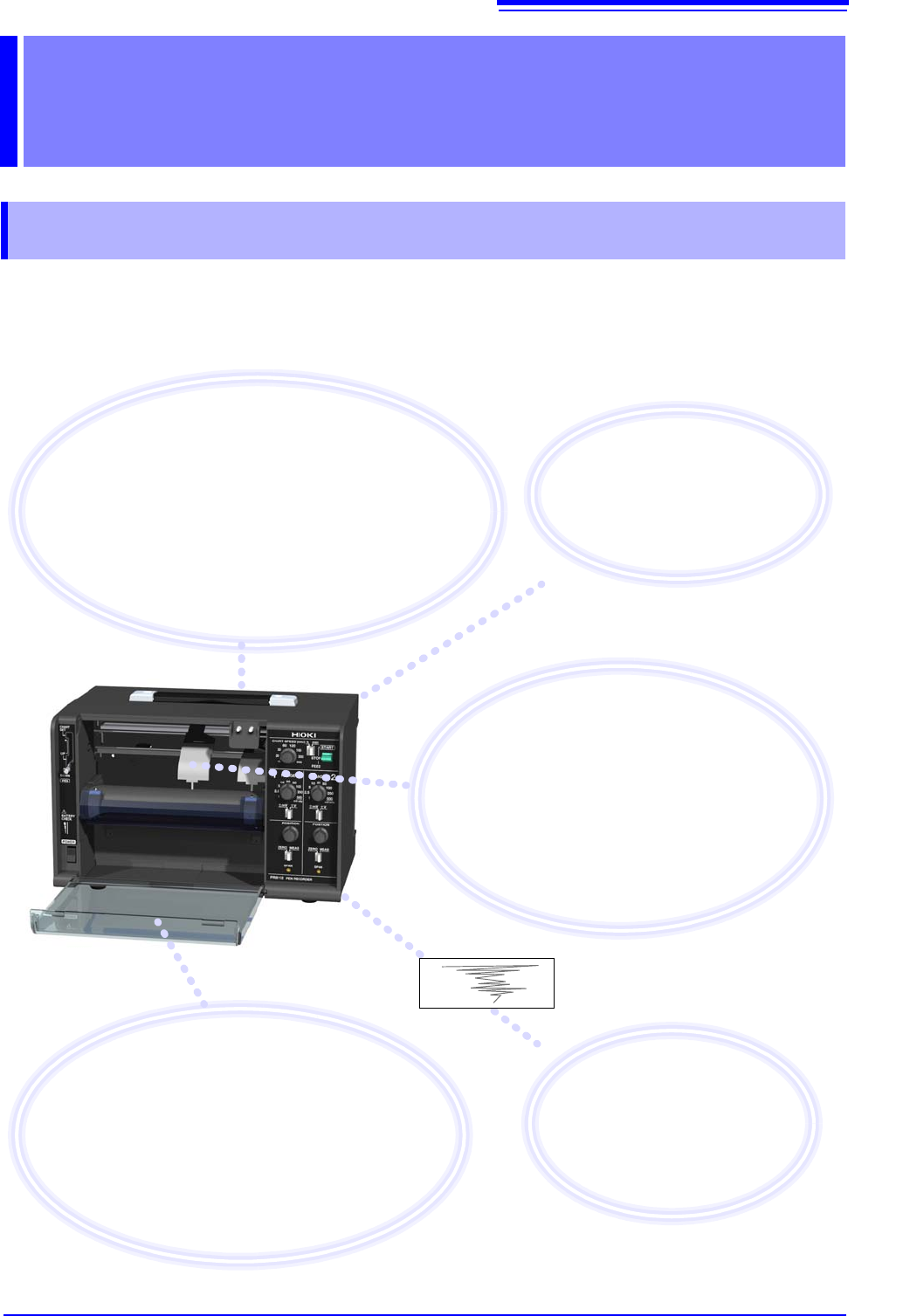
1.1 Product Overview and Features
Record, verify, and notate
measurement results in the field
Measurement results are recorded on paper, allowing
them to be easily verified. You can also make notes on the
paper in the field. Additionally, the instrument can measure
voltage output from other equipment, allowing it to be used
in maintenance applications such as corrosion prevention
systems. It can also record analog output, for example
from sensors and physics or chemistry instruments.
Assess changes in easy-to-see
color waveforms by watching
pen movements
The instrument can use red, green, and blue
pens (option). Waveforms are easy to see, even
outdoors, and can be stored for extended periods
of time. Additionally, you can assess waveform
changes in real time simply by watching the in-
strument’s pens as they move.
Preserve important recordings
Record with the front cover open to protect
recording paper from dirt on the ground.
Record with the front cover closed to keep out
dust and wind.
You can also use the included drip-proof vinyl
cover to protect the instrument from water
droplets and dust.
Select the power source
according
to your location
The instrument can be operated us-
ing either the AC adapter or dry-cell
batteries.
Easily compare and
verify results on paper
You can easily discover changes
and abnormalities by comparing
recordings with previously record-
ed waveforms.
1.2 Names and Functions of Parts
10
1.2 Names and Functions of Parts
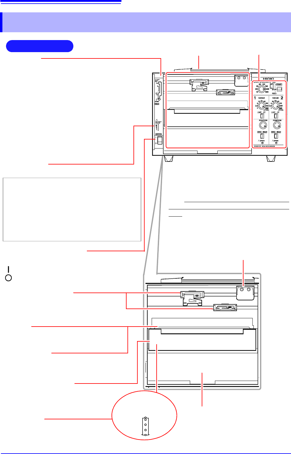
Front Panel
Handle
POWER switch (p. 19)
Turns the power on and off.
:Power OFF
:Power ON
Power LED
Lights up when the instrument is being supplied with power.
Green Lights up when power is being supplied by the
AC adapter. When using batteries, indicates
ample remaining battery life.
Orange Indicates limited remaining battery life. It is rec-
ommend to have new batteries ready to use.
Red Indicates low remaining battery life. It is recom-
mended to replace the batteries in the instru-
ment with new batteries.
Operating panel (p. 11)
Front cover (p. 21)
Keeps wind and dust out of the instrument.
The cover can be removed. It opens from above.
Note: When using roll paper, either remove the
front cover or use the instrument with the cover
open. Recording data with the front cover closed
may cause paper to jam in the chart tray.
(Example: PR8112)
Chart cover (p. 12)
Holds down the recording paper.
Chart holder
(Located underneath the platen)
Stores new recording paper. (p. 14)
Chart tray
Stores paper after waveforms have been
recorded. Fanfold paper will be folded here.
Pen holders (p. 16)
(Located toward the rear of the instrument)
Holds the pens. For more information about
compatible pens, see "Options" (p. 2).
Pen lever
• CHART SET (top)
Use when changing recording paper. The pens
will move up (away from the recording paper) and
to the right.
• UP (middle)
Use when changing pens or to disable recording.
The pens will move up (away from the recording
paper). Cap pens when not recording.
• DOWN (bottom)
Use when recording. The pens will be in contact
with the recording paper, allowing them to record
data.
Pen cap storage pins (p. 16)
Store caps on these pins while the pens are being
used so they don’t get lost.
Platen
Holds down the recording paper.
Sprockets
Feed the recording paper using a series
of holes along its edges.
When the chart
cover is open
1.2 Names and Functions of Parts
11
1
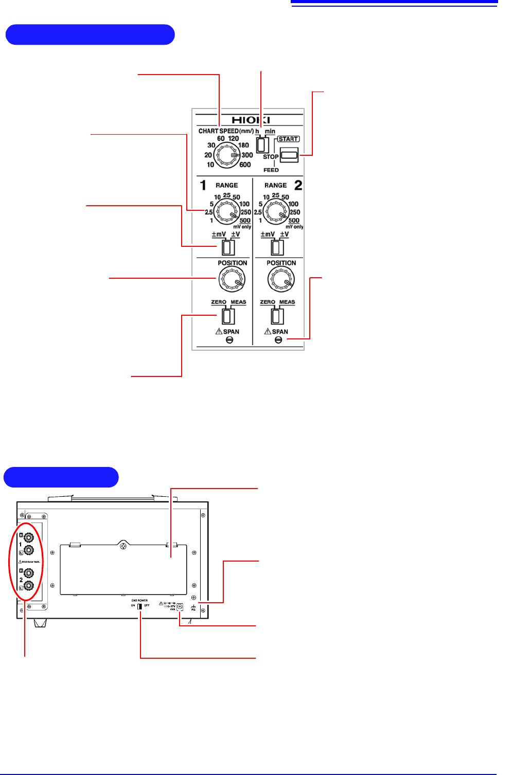
RANGE knob
Selects the measurement range, allowing
you to choose the range that best suits
the voltage being measured. The 500 set-
ting is used exclusively for mV ranges.
mV/V switch
Selects the unit for the measurement
range selected with the RANGE knob.
POSITION knob
Adjusts the pen’s zero point (0 V position)
by moving its position. When the ZERO/
MEAS switch is in the ZERO position, the
pen can be moved throughout the entire
effective recording width.
ZERO/MEAS switch
• MEAS: Use when measuring data. (You can start recording by placing
the START/STOP/FEED switch in the START position.)
• ZERO: Use when adjusting the pen’s zero point.
(You can move the position with the POSITION knob.)
CHART SPEED knob
Selects the chart speed, allowing you to
change the speed at which the recording
paper is fed through the instrument.
Operating Panel
h/min switch
Selects the unit for the speed set with the CHART SPEED
knob. You can select either minutes (min) or hours (h).
(Example: PR8112)
START/STOP/FEED
switch
Starts and stops the paper feed.
• START: Starts feeding paper through
the instrument.
• STOP: Stops feeding paper through
the instrument.
• FEED (by pushing the switch past
STOP): Feeds paper through the
instrument. There are four feed
speeds. You can increase the feed
speed by pressing and holding the
switch in the FEED position for at
least 2 seconds.
SPAN (p. 12)
Allows the recording width to be adjusted
using a screwdriver. This adjustment is
not usually used during normal operation.
Use as necessary when adjusting the in-
strument, for example during calibration.
• To increase the width: Turn clockwise.
(The recording width can be
increased by a maximum of about
20%.)
• To decrease the width: Turn counter-
clockwise. (The recording width can
be decreased by a maximum of about
20%.)
AC adapter terminal (p. 18)
Connect the included AC adapter here.
Battery bay and cover (p. 17)
When using batteries to power the instrument, load six
LR20 alkaline batteries here. Since the battery cover is
held in place with screws (M3), a Phillips head screw-
driver is required in order to change the batteries.
FG terminal
Use this terminal, which is connected to the instrument’s
metal chassis, to ground the chassis. For best grounding,
use a cable of 3 m or less in length.
Rear Panel
CH2 POWER switch (p. 26)
Use this switch (available only on the PR8112 [2-pen
model]) to turn CH2 (pen 2) off. Turning off CH2 lowers
the instrument’s power consumption when using only one
channel.
(Example: PR8112)
Input terminals (p. 20)
Connect the measurement cables here.
Red: Connect the cable carrying the high signal.
Black: Connect the cable carrying the low signal.
On the PR8112, the upper two terminals are CH1,
and the lower two terminals are CH2.
The PR8111 has only the upper two terminals.