PR8111、PR8112_user_manual_eng_20191015H.pdf - 第22页
2.5 Turning the Instrument On and Off 19 1 Once you have connec ted the instrument to i ts power suppl y or loaded batter ies, you can turn t he instrument on. 2.5 T urning the Ins trument On and Off Power ON Power OFF T…
2.4 Connecting the Power Source (Alkaline Batteries or AC Adapter)
18
Connect the Model 9418-15 AC Adapter and power cord that came with the instrument and then
connect the power cord to a wall outlet. When the adapter is used along with alkaline dry-cell batter-
ies, the AC adapter takes precedence. If the supply of power from the AC adapter is interrupted, the
instrument will switch over to battery power. When power returns, it will automatically revert to
power from the AC adapter.
You can also use the instrument with DC power source input, for example from an external battery.
The instrument can be powered with a 10 to 27 VDC signal from the AC adapter jack. Hioki can pro-
vide cables for this purpose on a special-order basis. For more information, please contact your
dealer or Hioki representative.
The cable connecting the battery and instrument should not exceed 3 m in length.
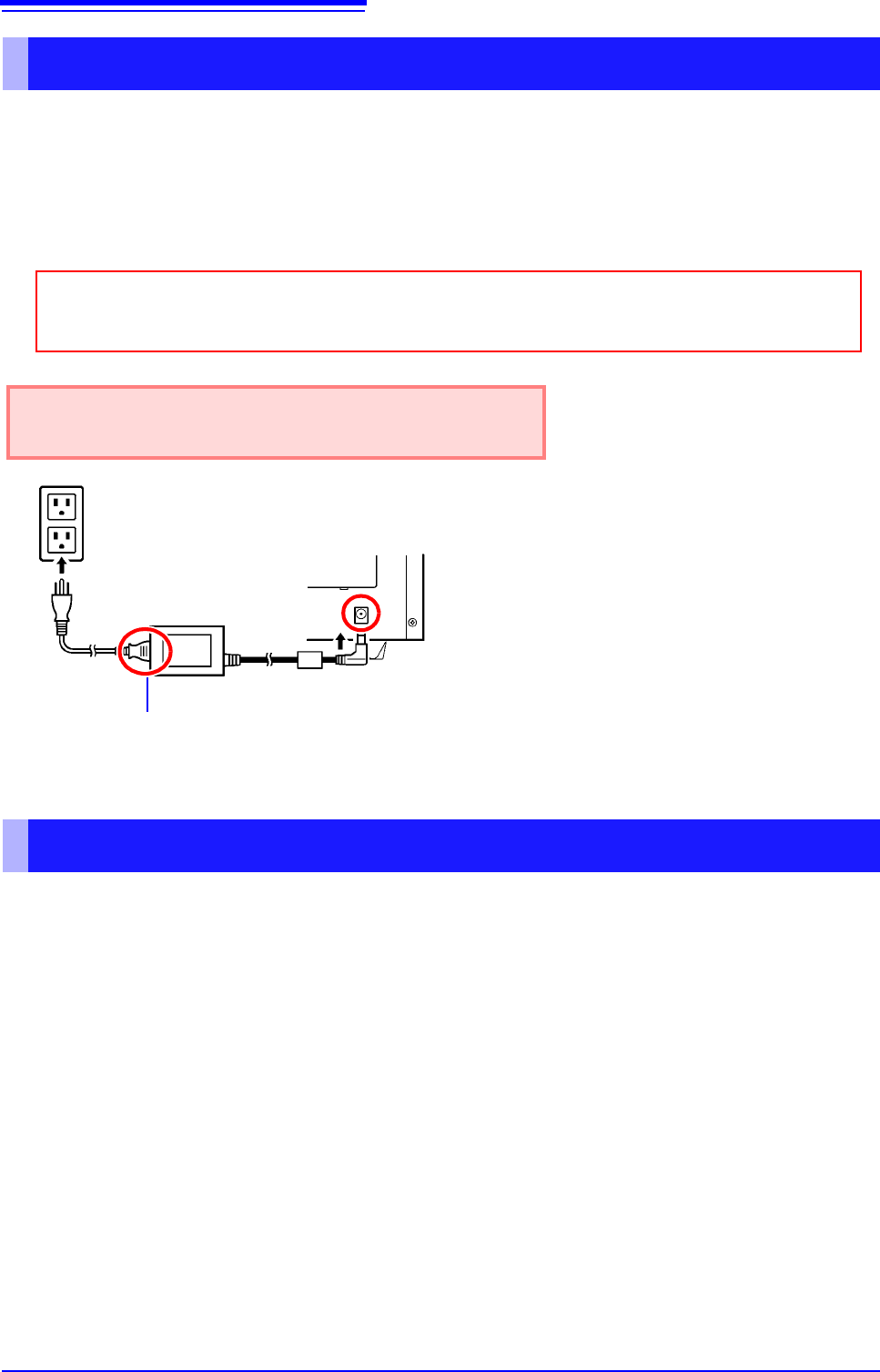
Connecting the AC adapter
Before connecting the AC adapter, be sure to read "Using the AC Adapter" (p. 7) and
"Handling the Cords and Cables" (p. 6).
Rated supply voltage is 100 to 240 VAC, and rated sup-
ply frequency is 50 or 60 Hz.
1
2
3
Power cord
AC adapter
1 Connect the power cord to the inlet socket
on the AC adapter.
2 Connect the output plug of the AC adapter
to the instrument.
3 Plug the power cord into the mains outlet.
Rear panel
Using a DC Power Source
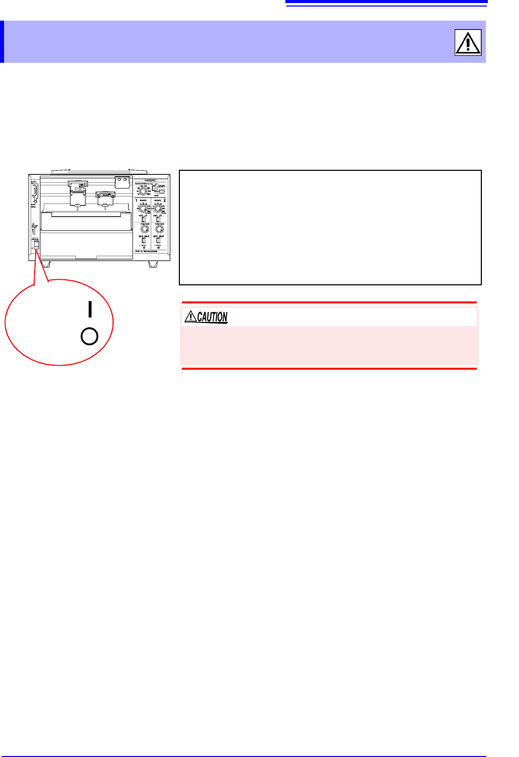
2.5 Turning the Instrument On and Off
19
1
Once you have connected the instrument to its power supply or loaded batteries, you can turn the
instrument on.
2.5 Turning the Instrument On and Off
Power ON
Power OFF
Turning on the instrument
Turn the POWER switch to the ON position.
Once the instrument has been turned on, the power supply LED will
light up.
Green Lights up when power is being supplied by the AC adapt-
er. When using batteries, indicates ample remaining bat-
tery life.
Orange Indicates limited remaining battery life. It is recommend to
have new batteries ready to use.
Red Indicates low remaining battery life. It is recommended to
replace the batteries in the instrument with new batteries.
Turning off the instrument
Turn the POWER switch to the OFF position.
If the orange or red LED lights up while using the AC adapter, the
instrument may be damaged. Stop all use and have the unit
repaired.
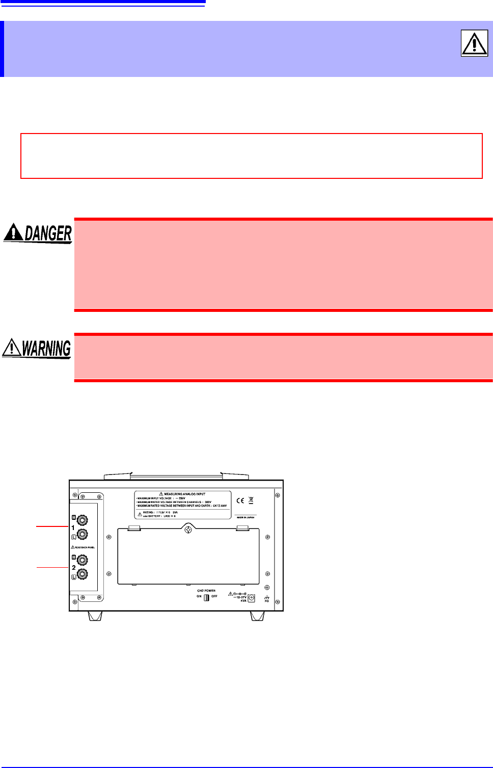
2.6 Connecting Measurement Cables to the Input Terminals
20
Connect the measurement cables to the measurement terminals on the rear of the instrument.
Wires with either crimp terminals or banana-plug cables can be connected.
How to connect cables
2.6 Connecting Measurement Cables to the
Input Terminals
Before connecting cables, be sure to read "Connecting Cables" (p. 8) and "Handling the
Cords and Cables" (p. 6).
• The maximum input voltage is 250 VDC. Attempting to measure voltage in excess
of the maximum input could destroy the instrument and result in personal injury or
death.
• The maximum rated voltage between input terminals and ground is 300 VAC, DC.
Attempting to measure voltages exceeding 300 V with respect to ground could
damage the instrument and result in personal injury.
To avoid experiencing an electric shock or causing a short-circuit at the input termi-
nals, only insulated crimp contacts should be used on wires being connected to
input pins. (The input terminal pin diameter is M6.)
CH1
(PR8112)
The PR8111 does not have terminals for CH2.
Connect the cables carrying high
signals to the red terminals.
Connect the cables carrying low
signals to the black terminals.
CH2