FRITSCH Pick and Place machine.pdf - 第18页
18 Usability and pr o gramming The clearly laid out softwar e guides the user step by step to his goal. T o setup a ne w pr oject or alter an existing one, the parameters can be simply chosen with a mouse click. There is…
17
Centering
systems
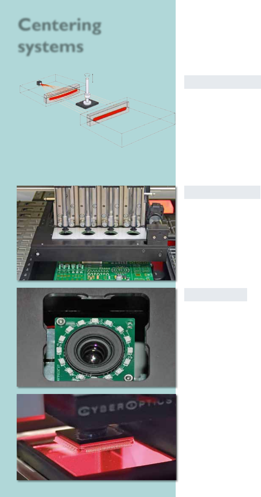
Laser centering
The laser centering is directely installed on the assembly
head. The component which has to be centered is while
rotating measured by the laser centering. Its shadow
on the opposite side is analysed and a contactless fast
centering happens. The component capability ranges
from 0201 chips up to components with dimensions
of 32 x 32 mm and Fine Pitch to 0.6 mm. BGAs can be
centered in this way, too.
The laser centering is also a method to determine the
component dimensions like length, width and height.
Vision On-The-Fly
With a max. component height of 20 mm and a width
of 14 x 14 mm the placeALL
®
700 offers due to its high-
speed-camera the possibility to center with On-The-Fly
up to four vision-components at the same time.
Bottom-Vision
The bottom vision is an image recognition which measu-
res and analyses the components what are to large for
the centering at the head.
The software for image recognition determines the exact
assembling position and tests the BGAs of complete balls
respectively that the FPs‘ wires aren‘t deformed. These
components can be selected before processing. Used are
components up to 0201, µBGAs, 0.3 mm Fine-Pitch or
special components like for example connectors.
Assembling tool
with component
Vision 2
Vision 1
18
Usability and programming
The clearly laid out software guides the user step by
step to his goal. To setup a new project or alter an
existing one, the parameters can be simply chosen with a
mouse click. There is also a detailed help menu for each
function.
The smartASSISTANT monitors all user activities, gives
hints and tips and shows every error source in plain
text, so it is generally not necessary to consult the user
manual.
Component library
The component library contains over 450 component
models. This represents one of the biggest libraries
on the market today. All content items can be
edited or new ones can quickly be created.
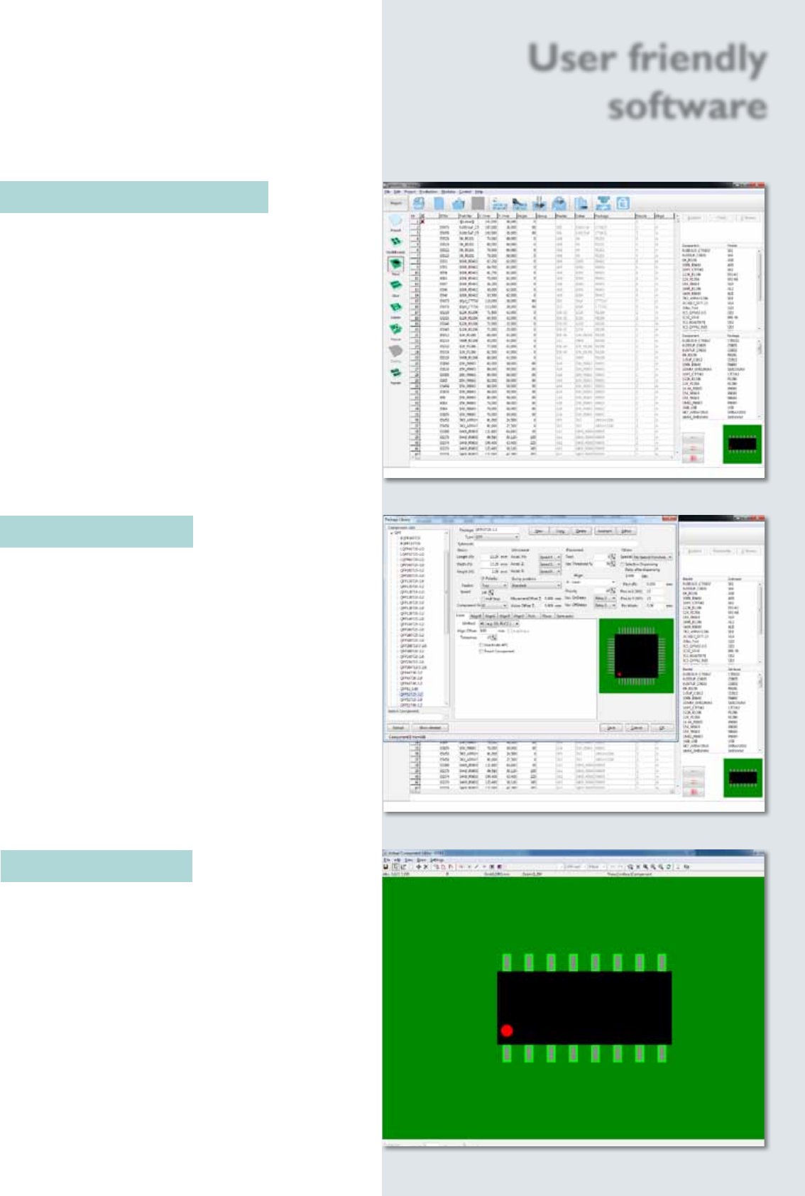
Component Editor
If components, which are not part of the default
library, need to be placed, a graphical editor is used to
create a new component body in just a few steps.
User friendly
software
19
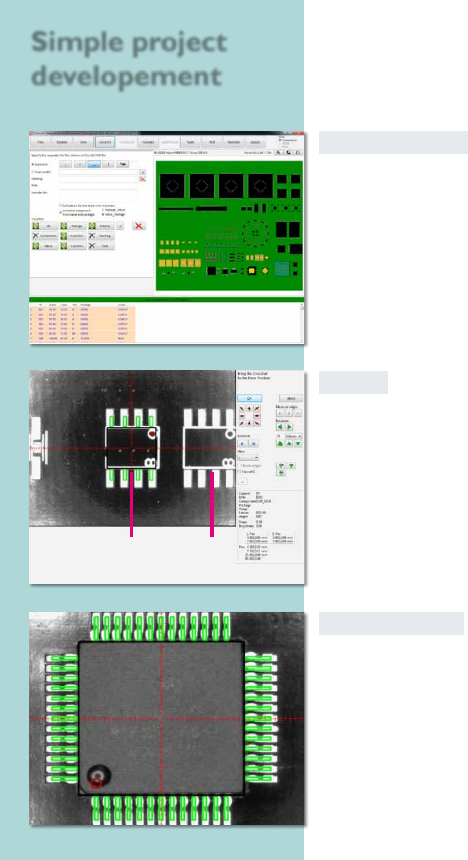
CAD data converter
CAD data from any CAD system can be interfaced easily
to the projects using a format editor. The conversion
process is very fast and can be done ofine on a separate
PC. During this process the Pick & Place machine
can continue to be used for its main task of placing
components.
Virtual Inspection
After acquiring the CAD data the virtual inspection
can be used to simulate the Pick & Place process. The
camera moves across the current circuit board. At
each placing position the corresponding component is
blended in virtually.
The position and polarity of the component can be
checked and corrected if necessary. In this way error-
free prototypes can be produced in a very short time.
Teach In
To create a project, the user drives the head to the
particular position; a virtual component is shown as an
overlay in the camera window. The virtual component
can now be adjusted exactly and brought into the right
position. After that, its position is logged into the
Pick & Place project le.
Simple project
developement
virtual component pads