FRITSCH Pick and Place machine.pdf - 第20页
20 Remote Suppor t Remote access to your machine b y our technicians is possible using the ser vice kit, after having y our appr oval. This connects us directl y into y our placeALL ® and the installed software to ra pid…
19
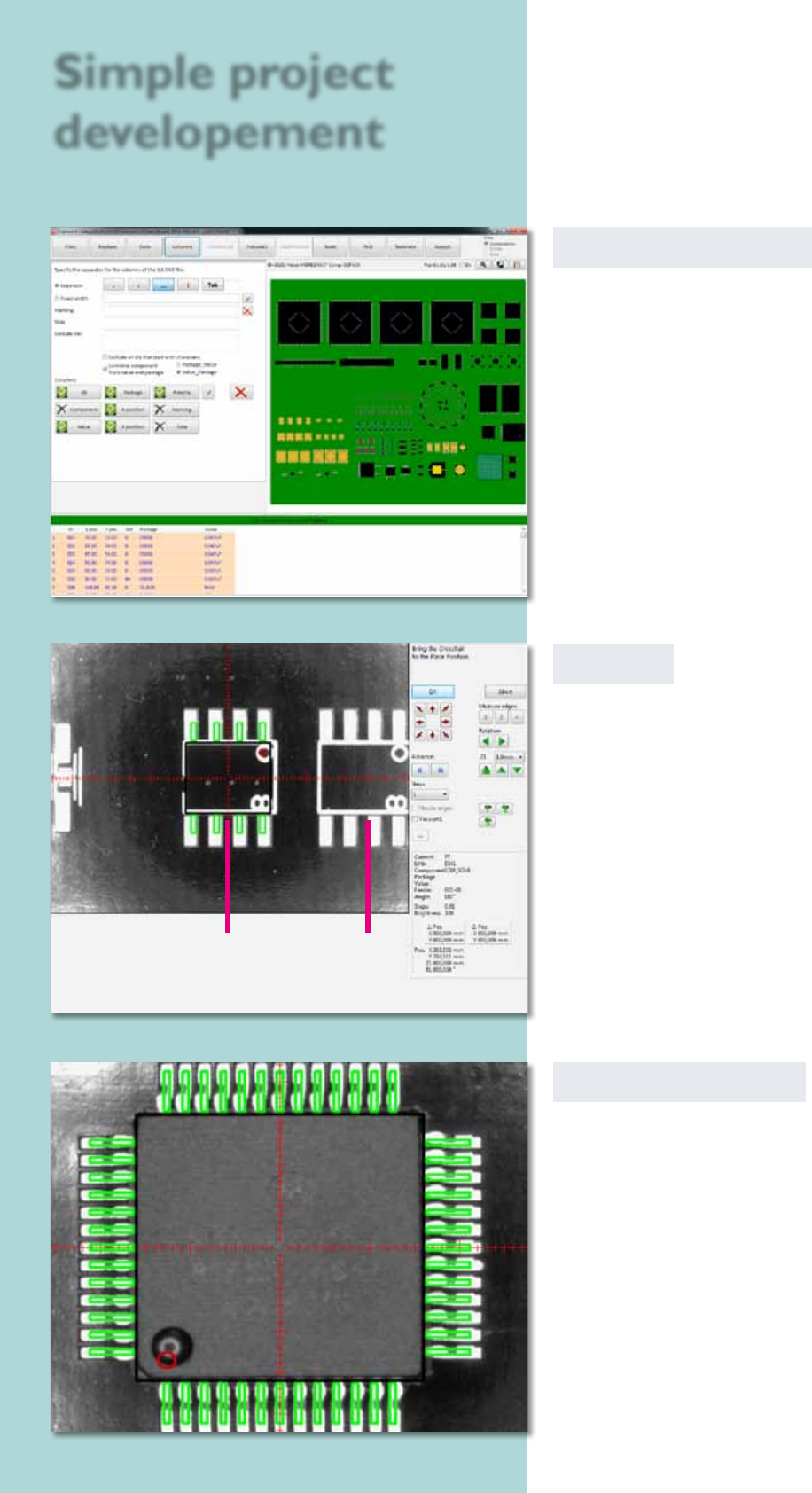
CAD data converter
CAD data from any CAD system can be interfaced easily
to the projects using a format editor. The conversion
process is very fast and can be done ofine on a separate
PC. During this process the Pick & Place machine
can continue to be used for its main task of placing
components.
Virtual Inspection
After acquiring the CAD data the virtual inspection
can be used to simulate the Pick & Place process. The
camera moves across the current circuit board. At
each placing position the corresponding component is
blended in virtually.
The position and polarity of the component can be
checked and corrected if necessary. In this way error-
free prototypes can be produced in a very short time.
Teach In
To create a project, the user drives the head to the
particular position; a virtual component is shown as an
overlay in the camera window. The virtual component
can now be adjusted exactly and brought into the right
position. After that, its position is logged into the
Pick & Place project le.
Simple project
developement
virtual component pads
20
Remote Support
Remote access to your machine by our technicians is
possible using the service kit, after having your approval.
This connects us directly into your placeALL
®
and the
installed software to rapidly provide an overview of the
machine’s status if any questions occur.
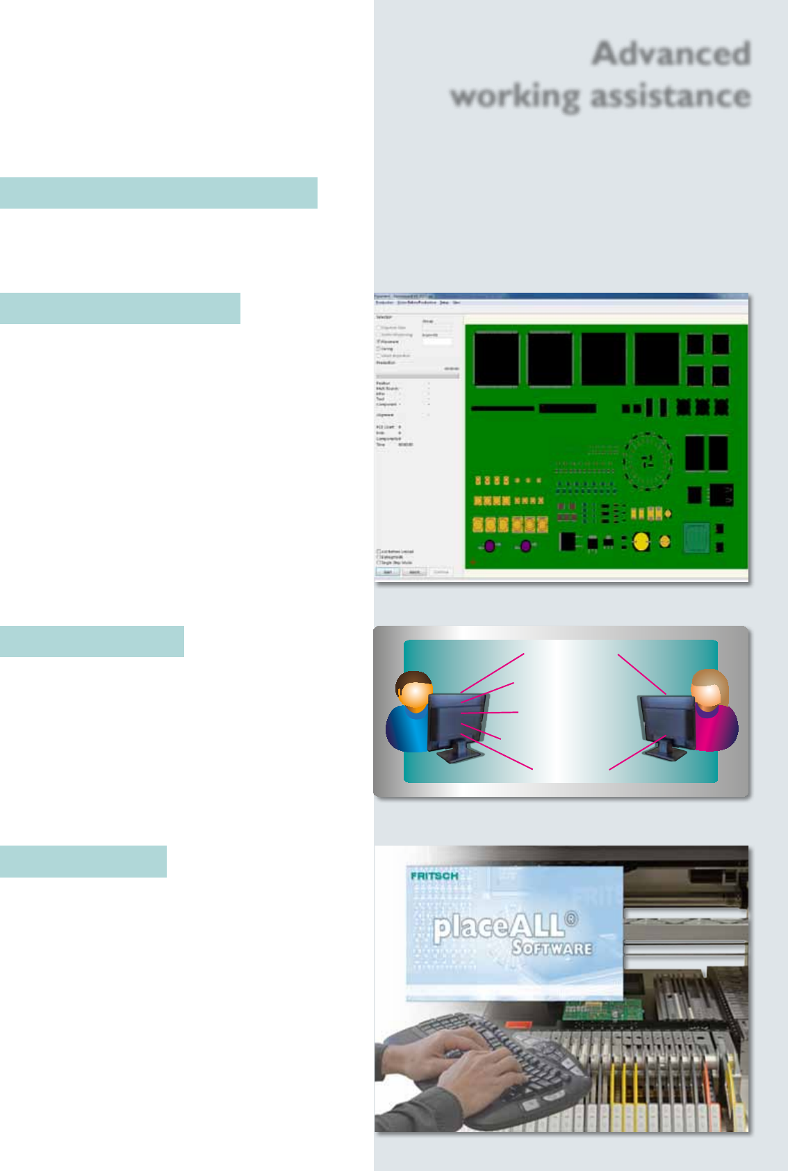
User management
The user administration makes it possible to assign
different rights to different users. The person who is
able to edit programs or update component libraries
can be dened, and other users can be locked out
of these functions. These rights can be easily edited
by clicking on the different production steps in the
software.
Monitoring the placement process
To inform the user of the current status of the Pick & Place
process, the circuit board is shown on the monitor. It
displays virtual components one-to-one with the real
assembly.
Automatic setup control
The automatic setup control shows the result be fore
the real assembly process starts.
The image of a PCB can be used as model. Therefore
it is possible to control fast and easy the result of
assembling.
Components are single or grouped deactivated or
deleted. The editor possibilities like moving or rotating
complete the automatic setup control to a very useful
tool. While the Pick & Place process the virtual plan is
displayed to control the real advancement of assembling.
Admin User
Start placement
Congurate project
Calibrate machine
Edit/create comp. model
Load project
Advanced
working assistance
21
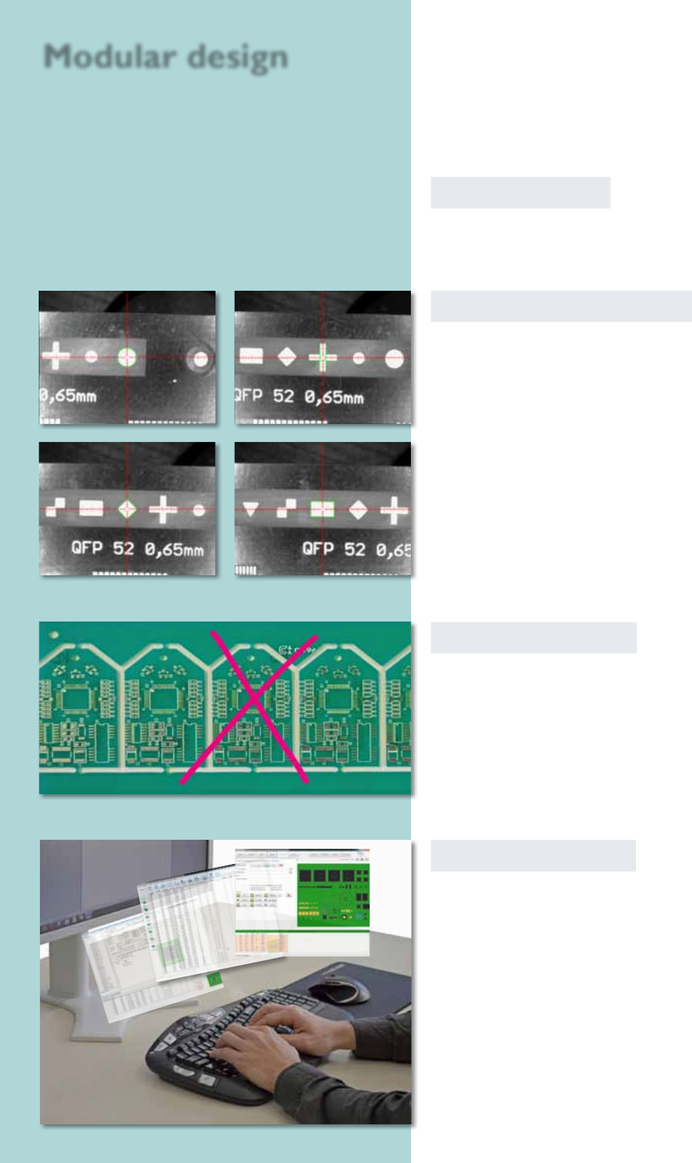
Autom. ducial recognition
To set up an assembly, reference marks such as crosses,
circles, rhombi etc. can be read in automatically. The
camera captures the exact position of the circuit board
before the assembly begins.
Software modules
All described software modules can be retted to
your software on demand.
circle
cross
rhomb rectangle
Badmark recognition
The recognition is searching automatically for a mark on
a dened position wether the PCB should by signed as
bad and shouldn‘t be assembled. The sign is identied in
cause of its brightness. Light or dark marks (made with
labels, pens or ink pints) can be recognized.
Ofine programming
With this CAD conversion, assembly and dispense data
as well as the whole libraries can be edited at a separate
workstation. The processed data can be transmitted to
the Pick & Place machine afterwards.
Modular design