00196591-04 UM S-Feeder Test Station EN.pdf - 第16页
Installation MTC 2 Initial Software Start 3.4.3 Connecting the Device Ground 16 User Manual SIPLACE S-Feeder Test Station 3.4.3 3 . 4 . 3 C o n n e c t in g t h e D e v ic e G r o u n d Connecting the Device Ground The d…
Installation MTC 2
3.4.2 Connecting the Serial Port for Data Exchange Connecting the S-Feeder Checking Device
User Manual SIPLACE S-Feeder Test Station 15
3.4.2
3.4.2 Connecting the Serial Port for Data Exchange
Connecting the Serial Port for Data Exchange
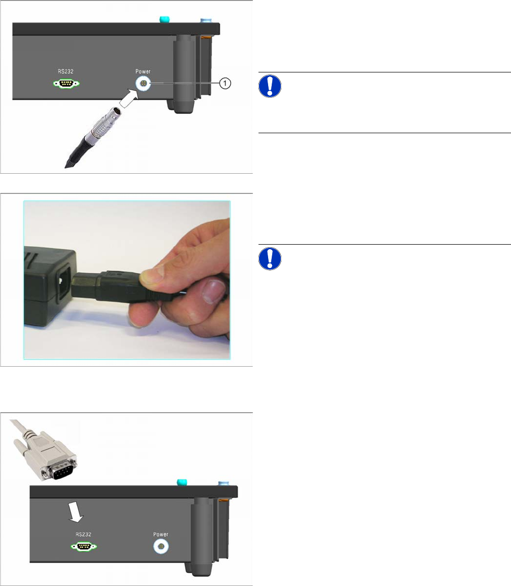
► Connect the Lemo plug of the power pack into the
right-and connection (Power) on the back of the
checking device.
Make sure that the red dot on the front of the plug is
at the top.
NOTICE! If you want to disconnect the plug:
Press the circlip (1) on the connection.
Hold the circlip pressed and pull out the plug.
► Plug the inlet connector into the power pack.
► Connect the power supply plug to an appropriately
grounded socket.
NOTICE! When connecting to the 110V supply,
you do not need to perform any conversions or switch
over the setting on the power pack.
► Connect one end of the serial cable (connector) to the
left connection (RS232) on the back of the checking
device.
Installation MTC 2
Initial Software Start 3.4.3 Connecting the Device Ground
16 User Manual SIPLACE S-Feeder Test Station
3.4.3
3.4.3 Connecting the Device Ground
Connecting the Device Ground
The device ground is used to discharge static energy.
3.4.4
3.4.4 Switching the Checking Device ON/OFF
Switching the Checking Device ON/OFF
3.5
3.5 Initial Software Start
Initial Software Start
► To start the
S-Feeder test software
, click on the following icon on the desktop of your PC:
The main
S-Feeder test software
window will be shown.
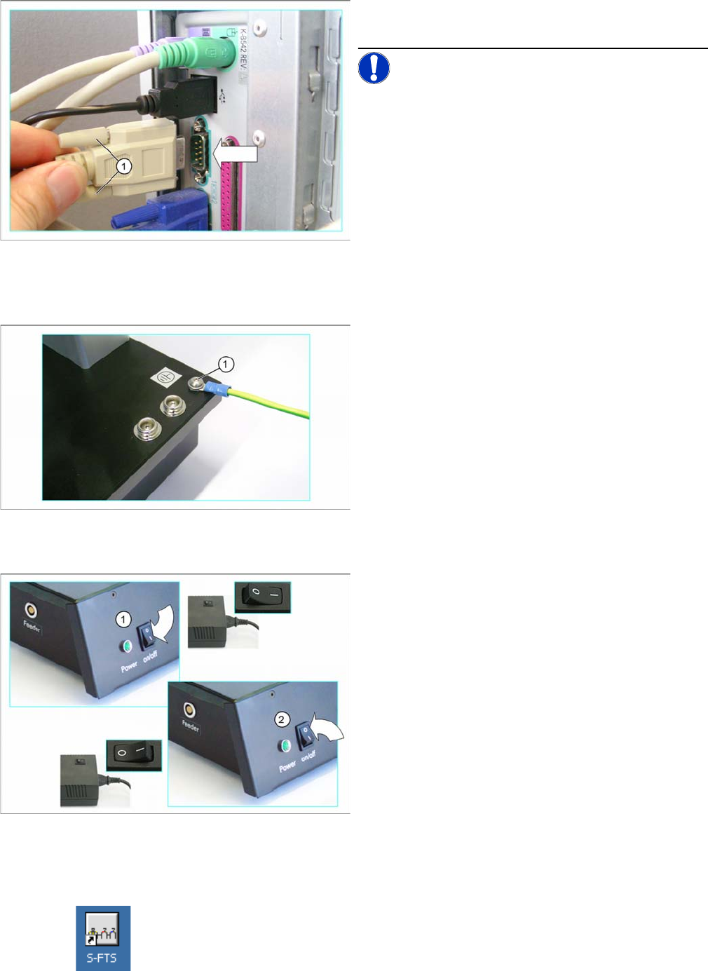
► Now connect the other end of the serial cable to the
serial port (COM1) on your PC.
NOTICE! If you want to use a different serial port
to COM1, you will then need to set this in the S-Feeder
test software, Tools menu, at Select COM port.
► Fasten the connector to the serial port, with the lock-
ing screws (1).
► Screw or plug a ground cable (1) into the checking
device.
► Connect the free end of the device ground cable to a
point at which the static energy can be discharged
(e.g. to the workbench).
Switching the checking device on
► Switch the power pack and the
S-Feeder Checking
Device
on at their respective ON/OFF switches (1).
The control lamp on the
S-Feeder Checking Device
will
shine. The device is now ready for operation.
Switching the checking device off
► Switch the
S-Feeder Checking Device
of at the ON/
OFF switch (2).
The control lamp on the
S-Feeder Checking Device
will
extinguish.
► Switch the power pack off.
Installation MTC 2
3.4.4 Switching the Checking Device ON/OFF Calibrating the Camera Position
User Manual SIPLACE S-Feeder Test Station 17
When you first start the
S-Feeder test software
, this checks the performance capacity of the USB port to
which the camera was connected and saves the max. achievable image transfer speed. This takes
roughly 20 seconds.
Now calibrate the camera position of the
S-Feeder Checking Device
(see "3.6 Calibrating the Camera
Position" [ ➙ 17]).
3.6
3.6 Calibrating the Camera Position
Calibrating the Camera Position
It is essential to calibrate the camera position of the
S-Feeder Checking Device
:
▪ If the
S-Feeder Checking Device
is connected to your PC for the first time.
When you start the
S-Feeder test software
you will see a corresponding message on your screen.
▪ If the
S-Feeder Checking Device
has been transported.
▪ If there are strong temperature fluctuations (> 5°C)
▪ Recommended: once a month.
If you want to view the date of the last calibration:
Open the Help menu with the command Info About S-Feeder Test station … and you will see an in-
formation window which shows the date of the last calibration plus other data.
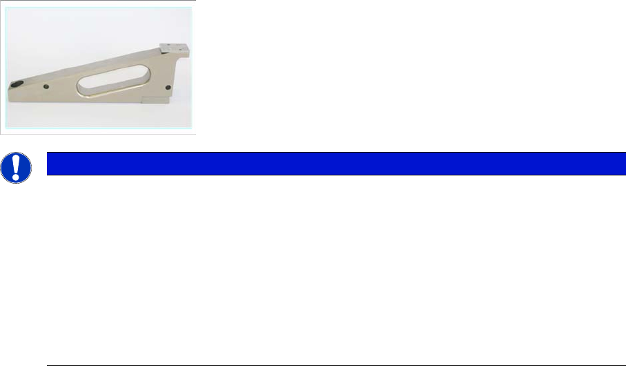
To calibrate the camera position, use the calibration standard supplied, item no. 03073729-01.
► Set the calibration standard to the receiving surface of the
S-Feeder Checking Device
(see "3.6.1
Setting up the Calibration Standard" [ ➙ 18] ).
► To start calibration, open the Tools menu and click on Calibrate.
calibration will be performed automatically and takes approx. 20 seconds.
► Once calibration of the camera position has been completed, remove the calibration standard from
the location surface of the
S-Feeder Checking Device
(see "3.6.2 Removing the Calibration Stand-
ard" [ ➙ 18] ).
What to do if calibration fails
If calibration of the camera position fails:
► Check the calibration standard.
Make sure that the reference plate on the top of the calibration standard is not dirty.
► Clean the location surface of the
S-Feeder Checking Device
and the underside of the calibration
standard. Remove any foreign bodies.
NOTICE
Adjusting the Pickup position
If you want to use the S-Feeder Checking Device to set the pickup position, observe the follow-
ing information:
Calibration should always be performed at the temperature at which you then want to test the
feeder modules. Tolerance: +- 5° C
To assimilate the temperatures, leave the S-Feeder Checking Device and the calibration stand-
ard unpacked at the installation site for 30 minutes before performing calibration.
To make sure that the calibration standard is in perfect condition, it should be checked every 2
years or if there is apparent damage. Send the calibration standard to the manufacturer for this
inspection.