00196591-04 UM S-Feeder Test Station EN.pdf - 第23页
Software Description 4.2.1 Live Image View File Menu User Manual SIPLACE S-Feeder Test Sta tion 23 Exiting the software To terminat e the cur rent session , click on the Close button. 4.2.1 4 . 2 . 1 L iv e I m a g e V i…

Software Description
Main Window
22 User Manual SIPLACE S-Feeder Test Station
On the right-hand side of the dialog box you will see a stationary image the configured feeder module.
The tape positions (A) and feeder fiducials (B) to be measured are marked by orange crosses. To refresh
the image, select the corresponding feeder module type again from the left.
Controls
(1) Mark the feeder module type to be tested in the list of feeder module types.
(2) The Pitch 4 mm [F4] button sets the step size of the 2x8 / 3x8 mm feeder modules to the size of 4
mm which is required for the test. All other feeder modules need to be set to 4 mm on the control panel
of the feeder module. For the correction of tooth position on the pin wheel, you can change the increment
on 2mm (shift F4).
(3) The Test feeder button starts the automatic test.
The feeder module tracks will be measured in order, one after the other.
For the correction of tooth position on the pin wheel, they can change the pitch on 2mm.
(4) In the Options menu, you can select the feeder module track. For example, if you have selected the
type 3x8 mm S at the top, you can then select the left (L), middle (M) or right track (R) from the list below.
With the buttons under the track selection list, you can manage the track selected above. Alternatively,
most test functions can also be accessed by pressing the corresponding function key.
(5) In this area, "read data feeder" they can press to load the data from the feeder and watch.
Status Display
At the bottom left of the dialog box you will see the current status of the
S-Feeder Checking Device
in
the form of a camera icon.
Messages
Notification messages are shown to the right of the camera icon e.g. if the USB camera is not connected
to the PC.
Live image feeder fiducial F8 This button takes you to the live image mode in which the position of
the feeder fiducial can be checked.
The other buttons in this dialog box are inactive (grayed out).
To exit the live image mode, click on this button again.
Live image tape position F7 This button takes you to the live image mode so that you can manually
check the play of the toothed wheel.
The other buttons in this dialog box are inactive (grayed out).
To exit the live image mode, click on this button again.
Single step F5 This button enables you to step the selected track one position on-
wards.
The results of the test will be shown as a static image in the main win-
dow.
Full revolution F3 This button enables you to step the selected track by one rotation of
the toothed wheel.
Eject tape - This button steps the selected track until the inserted test tape is eject-
ed. (maximum of 140 steps i.e. to the end of the test tape)
Cancel - This button terminates the test currently running. No results will be
shown.
Green:
The camera of the
S-Feeder Checking Device
is ready and the buttons on the user in-
terface are active.
Red:
The camera of the
S-Feeder Checking Device
is NOT ready and the buttons on the
user interface are NOT active.
Check whether the USB camera is correctly connected to your PC.
Software Description
4.2.1 Live Image View File Menu
User Manual SIPLACE S-Feeder Test Station 23
Exiting the software
To terminate the current session, click on the Close button.
4.2.1
4.2.1 Live Image View
Live Image View
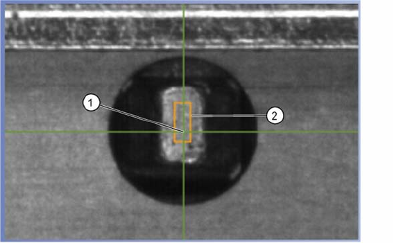
During the live image mode and the automatic test, you will see the image of the selected track and the
following details:
(1) The green cross shows the measured position of the middle of the hole.
If this position is outside the prescribed tolerance area, the cross will be red.
(2) The prescribed tolerance area is shown as an orange rectangle.
4.3
4.3 File Menu
File Menu
Terminating the Program
This command terminates the
S-Feeder test software
.
4.4
4.4 Menu Options
Menu Options
Pitch
This command starts a dialog in which you can set the step size of the feeder module to be tested.
Setting the Language
This command changes the language of the
S-Feeder test software
user interface. German and English
are available.
Select COM-Port
This command is used to select the COM port of your PC to be used for communication with the
S-Feed
-
er Checking Device
.
The preset COM port is COM1.
Function Test
With this command you can access additional test functions on the feeder. The test functions are de-
scribed in the Job Guide "JG S-Feeder Care Test Station".
Test without a feeder brand
This feature is only available for 2x8 mm S feeder. To a conveyor should not brand providing situational
awareness to be evaluated, here you can disable the detection of the brand. These conveyors must not
be used at the station with "conveyor position recognition"!
Feeder Manager Settings
Software Description
Help Menu 4.2.1 Live Image View
24 User Manual SIPLACE S-Feeder Test Station
This menu has been prepared for the proposed INTERFACE for Feeder Manager. Please note the de-
scription of the current Feeder Manager.
4.5
4.5 Help Menu
Help Menu
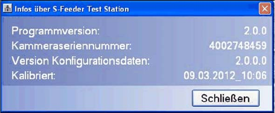
S Feeder test station
This command opens a dialog box showing information about your
S-Feeder Checking Device
.
To close this view, click on the Close button.
Programm Version Shows the
S-Feeder test software
version.
Device Shows the camera serial number.
Type Date Shows the configuration data version.
calibrated Shows the date on which the
S-Feeder Checking Device
was last calibrated.