00196591-04 UM S-Feeder Test Station EN.pdf - 第21页
Software Description Starting the Program User Manual SIPLACE S-Feeder Test Sta tion 21 4 4 S o f t w a r e D e s c r ip t io n Software Description 4.1 4 . 1 S t a r t in g t h e P r o g r a m Starting the Program ► To …
Installation MTC 2
Software uninstall 3.6.2 Removing the Calibration Standard
20 User Manual SIPLACE S-Feeder Test Station
Software Description
Starting the Program
User Manual SIPLACE S-Feeder Test Station 21
4
4 Software Description
Software Description
4.1
4.1 Starting the Program
Starting the Program
► To start the
S-Feeder test software
, click on the following icon on the desktop of your PC:
The main
S-Feeder test software
window will be shown.
Terminating the S feeder software
To terminate the
S-Feeder test software
, open the File menu and click on Exit.
4.2
4.2 Main Window
Main Window
After starting the
S feeder test software
you will see the following dialog box.
On the left side of the dialog box you will see operating controls with which you can set and start the test.
NOTICE
Starting the Software
Before you start the software, make sure that the S-Feeder Checking Device has been com-
pletely connected to your PC and the power supply.

Software Description
Main Window
22 User Manual SIPLACE S-Feeder Test Station
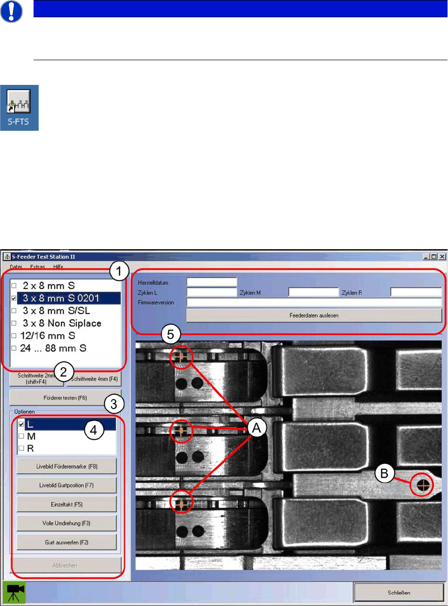
On the right-hand side of the dialog box you will see a stationary image the configured feeder module.
The tape positions (A) and feeder fiducials (B) to be measured are marked by orange crosses. To refresh
the image, select the corresponding feeder module type again from the left.
Controls
(1) Mark the feeder module type to be tested in the list of feeder module types.
(2) The Pitch 4 mm [F4] button sets the step size of the 2x8 / 3x8 mm feeder modules to the size of 4
mm which is required for the test. All other feeder modules need to be set to 4 mm on the control panel
of the feeder module. For the correction of tooth position on the pin wheel, you can change the increment
on 2mm (shift F4).
(3) The Test feeder button starts the automatic test.
The feeder module tracks will be measured in order, one after the other.
For the correction of tooth position on the pin wheel, they can change the pitch on 2mm.
(4) In the Options menu, you can select the feeder module track. For example, if you have selected the
type 3x8 mm S at the top, you can then select the left (L), middle (M) or right track (R) from the list below.
With the buttons under the track selection list, you can manage the track selected above. Alternatively,
most test functions can also be accessed by pressing the corresponding function key.
(5) In this area, "read data feeder" they can press to load the data from the feeder and watch.
Status Display
At the bottom left of the dialog box you will see the current status of the
S-Feeder Checking Device
in
the form of a camera icon.
Messages
Notification messages are shown to the right of the camera icon e.g. if the USB camera is not connected
to the PC.
Live image feeder fiducial F8 This button takes you to the live image mode in which the position of
the feeder fiducial can be checked.
The other buttons in this dialog box are inactive (grayed out).
To exit the live image mode, click on this button again.
Live image tape position F7 This button takes you to the live image mode so that you can manually
check the play of the toothed wheel.
The other buttons in this dialog box are inactive (grayed out).
To exit the live image mode, click on this button again.
Single step F5 This button enables you to step the selected track one position on-
wards.
The results of the test will be shown as a static image in the main win-
dow.
Full revolution F3 This button enables you to step the selected track by one rotation of
the toothed wheel.
Eject tape - This button steps the selected track until the inserted test tape is eject-
ed. (maximum of 140 steps i.e. to the end of the test tape)
Cancel - This button terminates the test currently running. No results will be
shown.
Green:
The camera of the
S-Feeder Checking Device
is ready and the buttons on the user in-
terface are active.
Red:
The camera of the
S-Feeder Checking Device
is NOT ready and the buttons on the
user interface are NOT active.
Check whether the USB camera is correctly connected to your PC.