00196591-04 UM S-Feeder Test Station EN.pdf - 第34页
Service Work Conveyor Replace the ring ligh t illumination board 6.1.3 Lighting adjustment 34 User Manual SIPLACE S-Feeder Test Station Assemble the camera body and carr y out the calibration. 6.1.3 6 . 1 . 3 L ig h t in…
Service Work Conveyor
6.1.2 Removal/installation of Lightning Board Replace the ring light illumination board
User Manual SIPLACE S-Feeder Test Station 33
Installation
Proceed with the installation in the reverse order of removal.
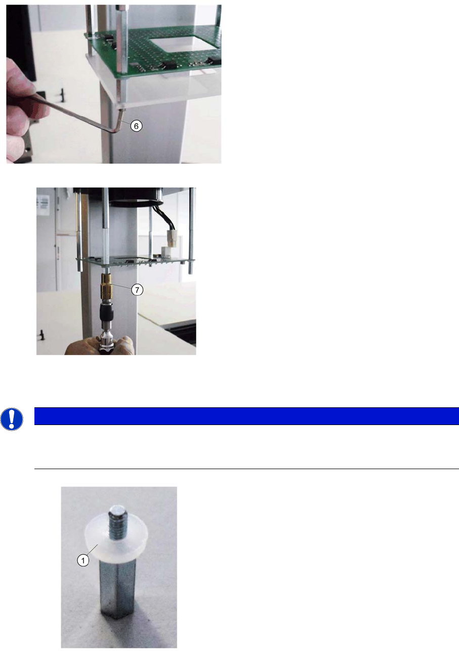
6. Open the 4 screws (6) of the focusing screen and
remove them.Loosen and remove the 6 fastening
screws from the guide rail.
7. Open the 4 bolts (7) of the lighting board and re-
move it.
The disassembly is completed
NOTICE
Observe correct installation.
Pay attention for installing the correct orientation of the modules, otherwise the correct mount-
ing is not possible.
1. Please do not forget the plastic washer (1) to the
stud
Note that there is a socket for the connection cable,
on the right side
Service Work Conveyor
Replace the ring light illumination board 6.1.3 Lighting adjustment
34 User Manual SIPLACE S-Feeder Test Station
Assemble the camera body and carry out the calibration.
6.1.3
6.1.3 Lighting adjustment
Lighting adjustment
Preparatory Steps
➢ The test station should be complete for calibration, with ground glass screen and camera body
mounted.
► Connect it to the power supply and connect it the USB - camera cable to the PC.
► Switch the machine on.
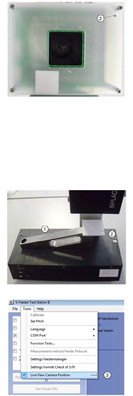
2. Observe the correct installation position of the
bushing (2) in the focusing screen!
Lousy must be located under the potentiometer of
the lighting board.
Tighten the mounting screws carefully!
Imagine the calibration part (1) onto the conveyor
pitch of the test station.
2. Put it the normal white 70x70 (2), as shown in the
picture on the calibration part ..
Avoid necessarily mean that the white standard is
dirty or damaged.
Avoid direct exposure to extraneous light - sources
such as ceiling or table lighting.
3. Start the test software and go to the menu "Ex-
tras" on "Live camera position.
The camera now turns on the lights
Leave the lights turned on for about 3 minutes be-
fore making the adjustment.
Service Work Conveyor
6.1.3 Lighting adjustment Replace the ring light illumination board
User Manual SIPLACE S-Feeder Test Station 35
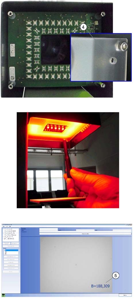
4. Put them on the potentiometer (4) the value B for
illuminance on 190 + -10.
To prevent a short circuit, the screwdriver should
not be conductive!
Depending on the type and strength of the ambient
light, the value can be falsified.
The dark it from the test station for the setting. But
use them to no reflective material!
Please take care on white normal, since it rests
loosely on the calibration part!
Use it a small adjustment screwdriver with a blade
width <1.5 mm and a thickness <0.4 mm.
Come with your fingers when adjusting the image
area of the camera!
5. Check them the value B (5) during the adjust-
ment. If they have 190 + -10 set, remove the screw-
driver and check it again the value.
Perform a machine calibration. Remove the
EDIF.Führen sie abschließend die Kalibrierung der
Kameraposition (Kapitel 3.6) durch. Entfernen sie
dazu das Weissnormal.