00196591-04 UM S-Feeder Test Station EN.pdf - 第25页
Operating the S-Feeder Test Station 5.2.1 Results display Performing the Test User Manual SIPLACE S-Feeder Test Sta tion 25 5 5 O p e r a t in g t h e S - F e e d e r T e s t S t a t io n Operating the S-Feeder Test Stat…
Software Description
Help Menu 4.2.1 Live Image View
24 User Manual SIPLACE S-Feeder Test Station
This menu has been prepared for the proposed INTERFACE for Feeder Manager. Please note the de-
scription of the current Feeder Manager.
4.5
4.5 Help Menu
Help Menu
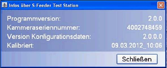
S Feeder test station
This command opens a dialog box showing information about your
S-Feeder Checking Device
.
To close this view, click on the Close button.
Programm Version Shows the
S-Feeder test software
version.
Device Shows the camera serial number.
Type Date Shows the configuration data version.
calibrated Shows the date on which the
S-Feeder Checking Device
was last calibrated.
Operating the S-Feeder Test Station
5.2.1 Results display Performing the Test
User Manual SIPLACE S-Feeder Test Station 25
5
5 Operating the S-Feeder Test Station
Operating the S-Feeder Test Station
5.1
5.1 Performing the Test
Performing the Test
For a detailed description of how to perform the test, refer to the
S-Feeder Test Station
job guide, item
no. 00196576-01.
When testing the feeder modules, always perform the individual steps in the following order:
1. Position the feeder module onto the location surface of the
S-Feeder Checking Device
and connect
it.
2. Select the feeder module type in the software.
3. If the tooth is not in the correct position, change the pickup position of the feeder module.
4. Set the step size of the track(s) to be tested to 4 mm.
5. Place the test tape in the track(s) to be tested.
6. Test the feeder module.
7. Wait for the test results and save these if required.
8. Start the automatic tape ejection process.
9. Remove the feeder module from the location surface of the
S-Feeder Checking Device
.
5.2
5.2 Evaluating the Test Results
Evaluating the Test Results
5.2.1
5.2.1 Results display
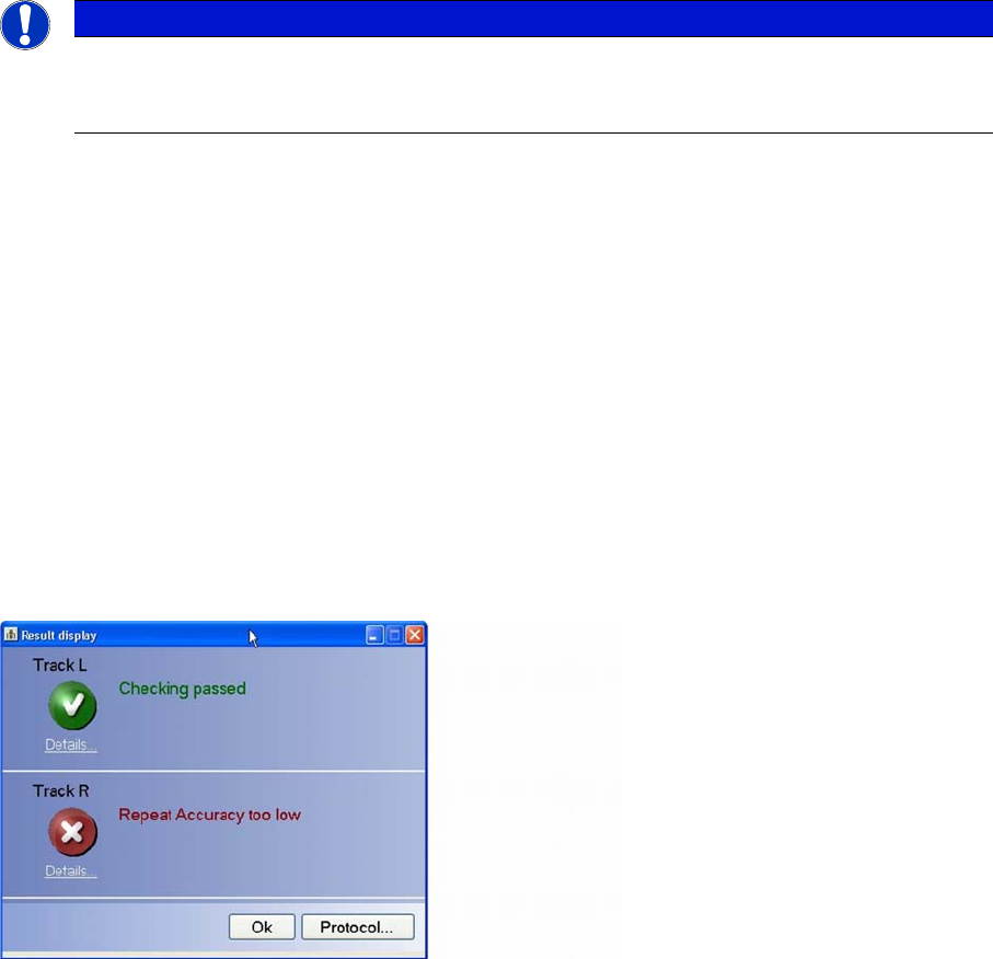
Results display
The overall results of the Test feeder function will be shown in a separate dialog box.
Each tested track is assessed separately. If an error has occurred at a particular track, the cause of this
error will be shown to the right of the icon (cross).
Click on Details to view the detailed test results for an individual track.
Click on the Protocol… button to view the whole test result as a PDF file which can then be saved and/
or printed out.
To make sure that you are able to clearly identify or assign the log file later on, enter the serial number
of the tested feeder in the dialog box.
NOTICE
Precondition
Precondition: the computer, power pack and S-Feeder Checking Device are switched on; the
S-Feeder Test Station software has started.
Operating the S-Feeder Test Station
Evaluating the Test Results 5.2.2 Detailed Measurements View
26 User Manual SIPLACE S-Feeder Test Station
5.2.2
5.2.2 Detailed Measurements View
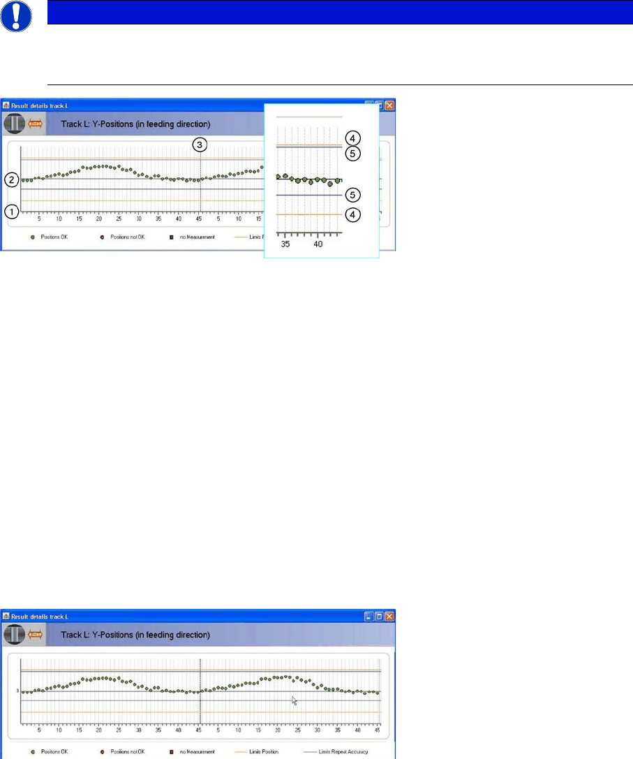
Detailed Measurements View
The upper part of the displayed graphic shows the position of the individual teeth in the direction of feed-
ing while the lower part shows the individual teeth across the direction of feeding.
The individual teeth of the toothed wheel are marked on the horizontal axis (1).
The horizontal black zero line (2) marks the target position of the individual teeth. In an ideal case, all
measurements would be on this line. The measured positions of the individual teeth are shown as dots.
The diagram shows two rotations of the toothed wheel. The broken black line running vertically (3) marks
the end of the first rotation.
There are two tolerance areas:
The two orange lines (4) mark the limits of the absolute tolerance area. The lines correspond to the or-
ange rectangle in the camera image. These lines have a fixed position.
The two blue lines (5) mark the limits of the repeat accuracy. These lines can be shifted according to the
average value of all measurements. The repeat accuracy is primarily affected by the following three fac-
tors:
▪ Gear play
▪ Roundness of the toothed wheel
▪ Deformation of the teeth
The green dots show the measuring results which are inside the two tolerance areas.
The red dots show measuring values which are outside at least one of the tolerance areas.
Red squares show positions at which measurement failed.
In the diagram shown, all measurements are within the two tolerance areas.
The measurements are generally shifted slightly upwards. On the feeder, this corresponds to a shift in
pickup position forwards, in the direction of transport.
The measurements show a sinusoidal character in both rotations i.e. the toothed wheel is not perfectly
round.
The measurements from the first and second rotation largely correlate, indicating that the gear play is
minor.
NOTICE
Type and source of danger
The following examples only show the top half of the diagram. The description applies equally
to the bottom half of the diagram.