00196591-04 UM S-Feeder Test Station EN.pdf - 第6页
Introduction Accessories 6 User Manual SIPLACE S-Feeder Test Station 1.3 1 . 3 A c c e s s o r ie s Accessories 00196590-03 The following accessories are a vailable as options: ▪ Calibration standard , item no. 03073729-…
Introduction
General
User Manual SIPLACE S-Feeder Test Station 5
1
1 Introduction
Introduction
1.1
1.1 General
General
For optimum organization of your products, you need to ensure the smooth and reliable use of your feed-
er modules. You can achieve this by regularly checking your feeder modules, cleaning them when nec-
essary, servicing them and making sure that they are set correctly. These measures can significantly
reduce unscheduled downtime.
The
S-Feeder Test Station
consists of a testing device (
S-Feeder Checking Device
) and software sup-
port. The
S-Feeder Test Station
enables you to check the reliable process and functionality of your S
feeder modules with the help of an electronically supported sight check. This determines the current val-
ues and compares them to predefined tolerance values.
If the check finds that tolerance values have been exceeded, we recommend that you send the feeder
modules concerned for repair.
The
S-Feeder Test Station
can be used to check:
▪ The general functionality of the feeder modules
▪ The position of the teeth in the respective toothed wheel (pickup position)
▪ The play of the toothed wheel in the and across the direction of feeding
The
S-Feeder Test Station
is designed for use with the following
SIPLACE
feeder modules:
1.2
1.2 Scope of Delivery
Scope of Delivery
The
S-Feeder Test Station
is delivered with the following:
▪1
S-Feeder Checking Device
, item no. 03071323-01
▪ 1 power pack, item no. 03041682-01
▪ 1 serial cable, item no. 03040362-01
▪ 1 set of testing tapes, item no. 03074708-01
▪ 1 CD with the
S-Feeder test software
, item no. 03076718-04
▪ 1 operating manual, item no. 00196590-03
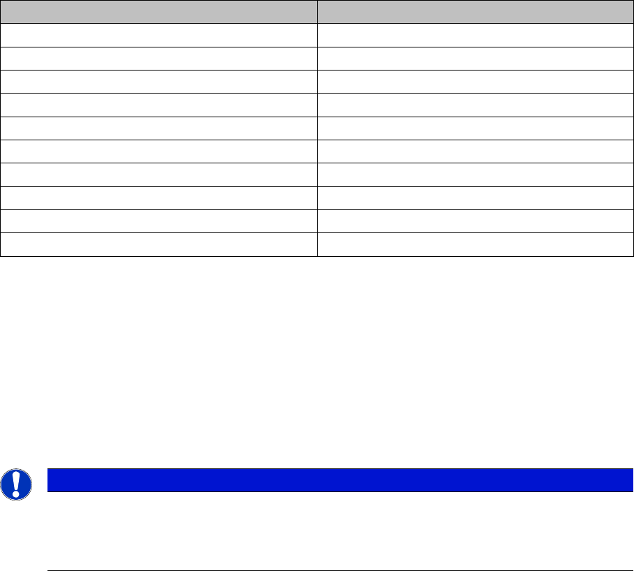
Designation Item no.
2 x 8 mm S II 00141096-xx
3 x 8 mm S 00141098- xx
3 x 8 mm SL 00141088- xx
3 x 8 mm S; 0201/0402 00141099- xx
12/16 mm S 00141092- xx
24 / 32 mm S 00141093- xx
44 mm S 00141094- xx
56 mm S 00141095- xx
72 mm S 00141097- xx
88 mm S 00141070- xx
NOTICE
Operation
To use the S-Feeder Test Station, you need to have the calibration standard, item no.
03073729-01 (available as a separate option). This calibration standard is not supplied with the
feeder module as you only need one of these at each factory.enthalten
Introduction
Accessories
6 User Manual SIPLACE S-Feeder Test Station
1.3
1.3 Accessories
Accessories
00196590-03
The following accessories are available as options:
▪ Calibration standard, item no. 03073729-01
▪ Set of 8 mm master tapes, item no. 03074715-01
▪ Set of 12/16 mm master tapes, item no. 03074717-01
1.4
1.4 EU Declaration of Conformity
EU Declaration of Conformity
The checking device is in conformity with the regulations and standards specified in the EU Declaration
of Conformity
Manufacturer:
ASM Assembly Systems
Rupert-Mayer-Str. 44
D-81359 München
1.5
1.5 Use of Symbols
Use of Symbols
Conventions for the Use of Hazard Symbols
Model Checking and setting device
Type S-Feeder Checking Device
Item No. 03071323-01
This typeface Marks controls and interface elements in the software.
Marks tasks which are to be performed by the user
NOTICE
Notice
as used in this Operation Manual provides information on the product or indicates a part of the
Operation Manual that requires particular attention.
CAUTION
Caution
as used in this Operation Manual means that slight injury or damage to equipment may occur
if the caution instructions are not followed.
WARNING
Warning
as used in this Operation Manual means that death, severe injury or considerable damage to
equipment may occur if the warning instructions are not followed.
Introduction
Safety Instructions
User Manual SIPLACE S-Feeder Test Station 7
1.6
1.6 Safety Instructions
Safety Instructions
1.7
1.7 Installation Location
Installation Location
▪ Stand the device on a stabile, sturdy table in your production environment.
▪ Make sure that you have enough room to the left of the device so that you can insert the test tapes
into the feeder modules.
▪ In order to minimize heat and external light, avoid direct sunlight on the device.
Permissible temperature range
For checking the feeder modules: +15°C - +35°C
For setting the feeder modules: +18°C - +25°C
WARNING
Safety Note
The safety instructions in the manual for the relevant SIPLACE S feeder module take prece-
dence. This instruction manual and the safety information within are targeted at use of the
checking device and the feeder module, separately from the machine .
The "external feeder module power supply" is connected to the 230V AC (Europe) / 110V AC
(USA); 50/60 Hz line power supply. When connecting to the 110V supply, you do not need to
perform any conversions or switch over the setting on the power pack.
Technical data for external power supply:
Power output:130 Watt
Input nominal current (max.): 3.2 A
Output nominal current (max.): 4.3 A
The "external feeder module power supply" must not be opened or manipulated.! (Danger of
electric shock)
Always observe the applicable accident prevention and VDE regulations, plus the specific safe-
ty regulations for handling laboratory equipment and systems outside the machine, as applica-
ble in your country.
CAUTION
Purpose of Use
The checking device may only be used to test those feeder modules approved for its use.
The checking device may only be modified or repaired by the manufacturer.
The setting screws are sealed. If the setting screws are loosened or the seal is damaged, any
claims for warranty will be invalidated and cancelled.
Always observe the warnings and safety instructions in the chapters of this manual.
Always transport the testing device in its original packaging.
In order to work safely with the testing and setting device, place it down on a suitably stable and
solid table.
CAUTION
Master Tapes
The test tapes are made of metal. Do NOT handle these near live parts.
CAUTION
Moving the Checking Device
Always carry the checking device by holding on to it at the left and right of the housing! The
device for visual testing (camera tower) is sensitive and NOT suitable for carrying the checking
device.