00196591-04 UM S-Feeder Test Station EN.pdf - 第27页
Operating the S-Feeder Test Station 5.2.3 Error Images Evaluating the Test Results User Manual SIPLACE S-Feeder Test Sta tion 27 5.2.3 5 . 2 . 3 E r r o r I m a g e s Error Images 5.2.3.1 5 . 2 . 3 . 1 M e a s u r e m e …
Operating the S-Feeder Test Station
Evaluating the Test Results 5.2.2 Detailed Measurements View
26 User Manual SIPLACE S-Feeder Test Station
5.2.2
5.2.2 Detailed Measurements View
Detailed Measurements View
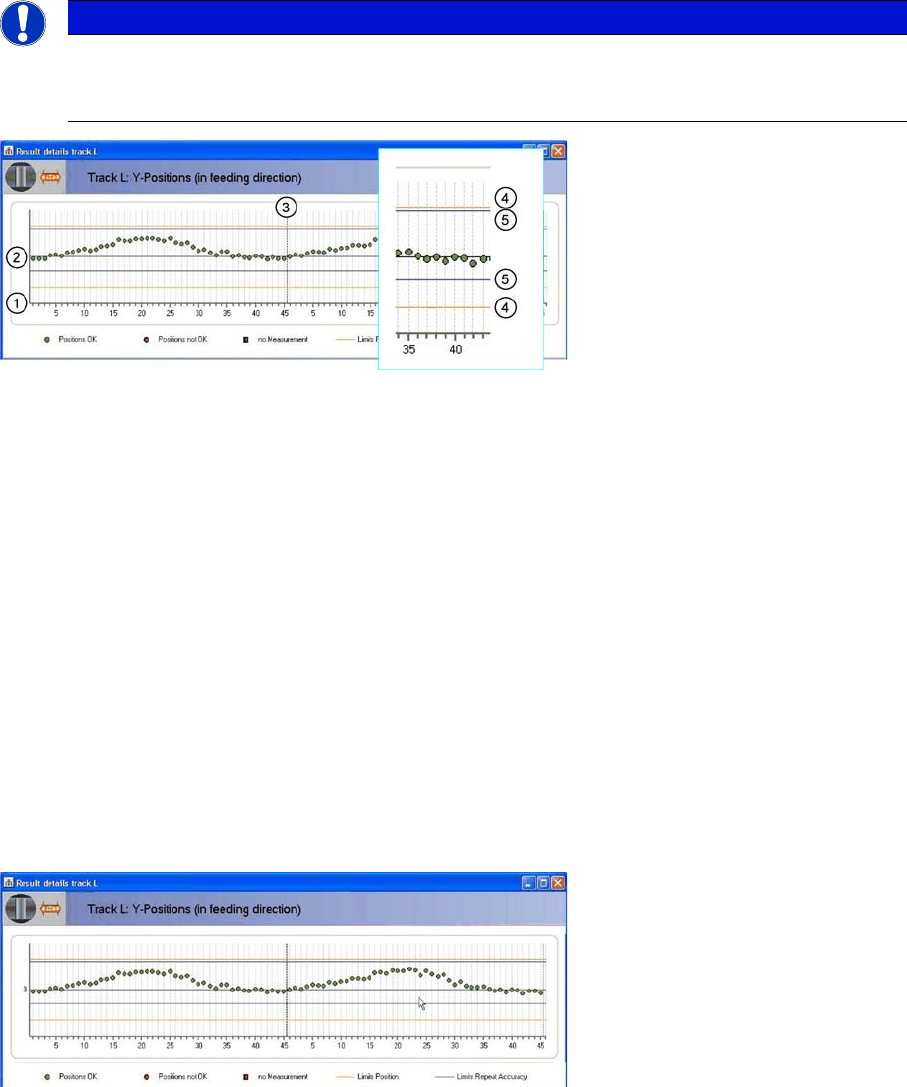
The upper part of the displayed graphic shows the position of the individual teeth in the direction of feed-
ing while the lower part shows the individual teeth across the direction of feeding.
The individual teeth of the toothed wheel are marked on the horizontal axis (1).
The horizontal black zero line (2) marks the target position of the individual teeth. In an ideal case, all
measurements would be on this line. The measured positions of the individual teeth are shown as dots.
The diagram shows two rotations of the toothed wheel. The broken black line running vertically (3) marks
the end of the first rotation.
There are two tolerance areas:
The two orange lines (4) mark the limits of the absolute tolerance area. The lines correspond to the or-
ange rectangle in the camera image. These lines have a fixed position.
The two blue lines (5) mark the limits of the repeat accuracy. These lines can be shifted according to the
average value of all measurements. The repeat accuracy is primarily affected by the following three fac-
tors:
▪ Gear play
▪ Roundness of the toothed wheel
▪ Deformation of the teeth
The green dots show the measuring results which are inside the two tolerance areas.
The red dots show measuring values which are outside at least one of the tolerance areas.
Red squares show positions at which measurement failed.
In the diagram shown, all measurements are within the two tolerance areas.
The measurements are generally shifted slightly upwards. On the feeder, this corresponds to a shift in
pickup position forwards, in the direction of transport.
The measurements show a sinusoidal character in both rotations i.e. the toothed wheel is not perfectly
round.
The measurements from the first and second rotation largely correlate, indicating that the gear play is
minor.
NOTICE
Type and source of danger
The following examples only show the top half of the diagram. The description applies equally
to the bottom half of the diagram.
Operating the S-Feeder Test Station
5.2.3 Error Images Evaluating the Test Results
User Manual SIPLACE S-Feeder Test Station 27
5.2.3
5.2.3 Error Images
Error Images
5.2.3.1
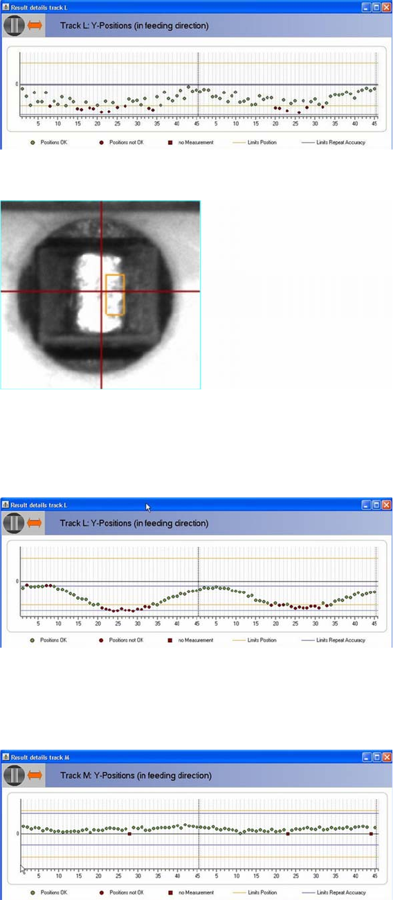
5.2.3.1 Measurements Outside the Tolerance
Measurements Outside the Tolerance
Some of the measurements are outside the absolute tolerance area. These values can be recognized
in the image during the measurement: the cross is outside the orange rectangle and is shown in red.
► Readjust the pickup position of the track.
The measurements spread between the first and second rotation. This indicates a more major gear play.
This feeder only just keeps to the repeat accuracy.
5.2.3.2
5.2.3.2 Repeat Accuracy Insufficient
Repeat Accuracy Insufficient
Some of the measurements in the diagram shown violate both the limits for the repeat accuracy and
those of the absolute tolerance area. In this case, both the play and the pickup position need to be reset
for the toothed wheel.
5.2.3.3
5.2.3.3 Unable to Measure At Least 3 Points
Unable to Measure At Least 3 Points
If the software is unable to determine a position three times during measurements, this will be acknowl-
edged with the corresponding message.
Operating the S-Feeder Test Station
Evaluating the Test Results 5.2.3 Error Images
28 User Manual SIPLACE S-Feeder Test Station
► In this case, repeat measurement with a new test tape.
5.2.3.4
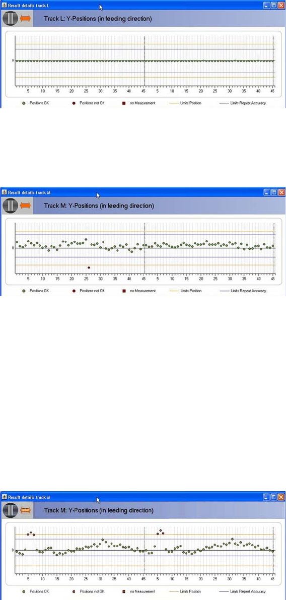
5.2.3.4 Toothed Wheel Did Not Move
Toothed Wheel Did Not Move
If all measured teeth are at exactly the same position, this indicates that the toothed wheel has not
moved. This is recognized by the software and acknowledged with the corresponding message.
► siftradThe feeder module needs to be repaired.
5.2.3.5
5.2.3.5 Individual Measurements Deviate Greatly
Individual Measurements Deviate Greatly
In the diagram shown, the measurement at tooth 26 deviates greatly from the other values during the
first rotation. This indicates that the measuring tape is defective or that there are components jammed
between the teeth.
► In this case, repeat measurement with a new test tape.
If the measurement shows the same deviation during both rotations, check whether there are compo-
nents on the toothed wheel:
► Move the pickup position over the operating panel of the feeder by 2 mm, so that the spaces between
the teeth are visible.
► Start a "full rotation" (F3) and check the image shown for components.
If you see components, step with "Single step" (F5) to the points affected and remove the components.
► Move the pickup position over the operating panel of the feeder by another 2 mm and repeat the test.
5.2.3.6
5.2.3.6 Multiple Measurements in Sequence Deviate Greatly
Multiple Measurements in Sequence Deviate Greatly
In the diagram, several measurements deviate greatly from the other values. This could have the follow-
ing causes:
There are components on the toothed wheel.
► Remove the components.
The measuring tape is damaged. A wrong measuring tape was used.