cp642规格书.pdf - 第14页
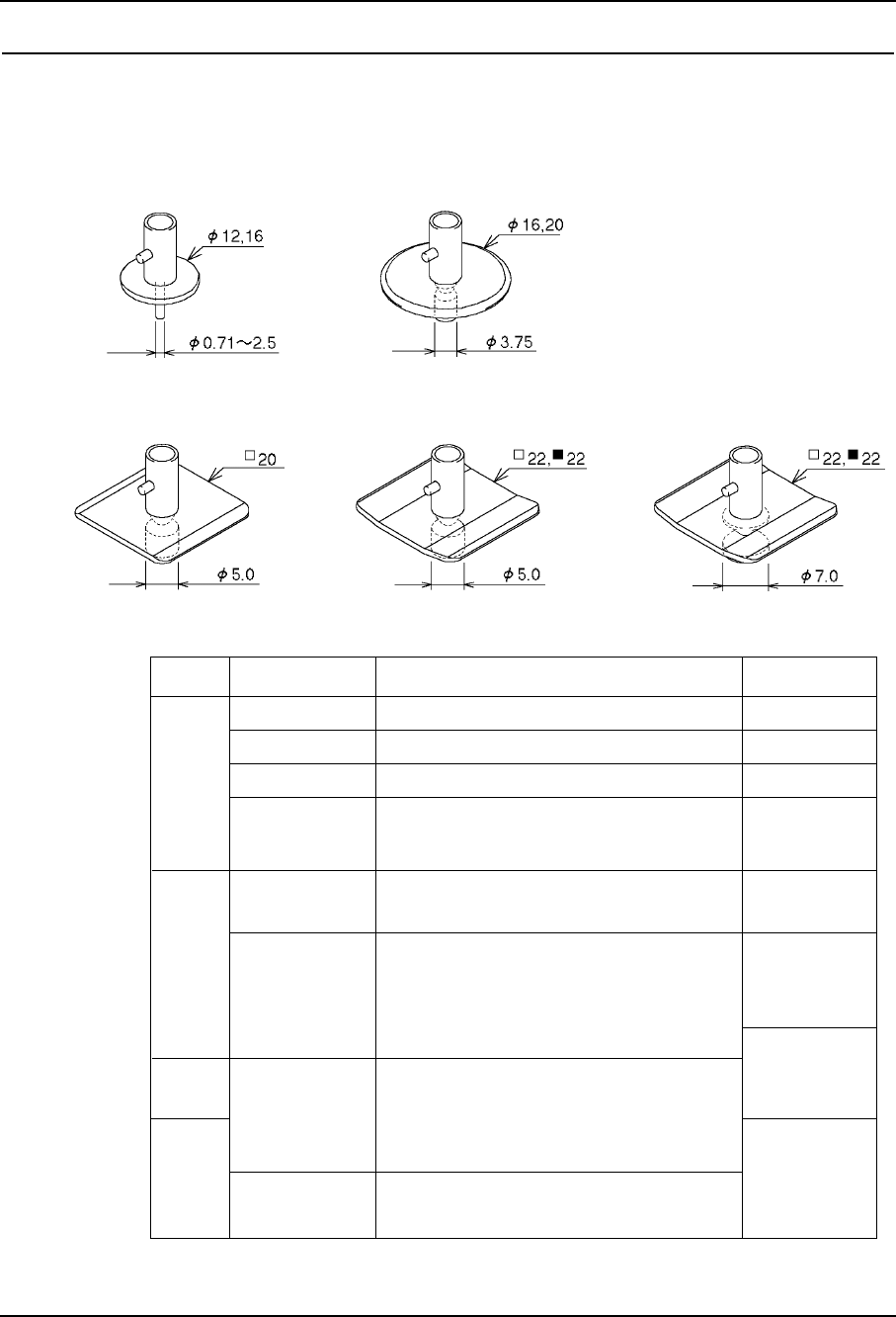
5. Nozzle Notes: (1) The letter in "Nozzle name" denotes the shape of the diffuser (except M&B). R : Round (back light) M : Special nozzle for Melf (back light) S : Square (back light) B : Square (front lig…
5. Nozzle
5.1 Nozzle and Nozzle Assembly
(1) Each placing head carries up to 6 nozzles of different types, selected from a range of
15.
(2) Refer to the following table for nozzle types and applicable parts.
1005, 1608, SSMIN
1608, 2125, SMIN, MIN
2125, 3216, MIN, Tantalum A, Melf
3216, 3225, 4532, Tantalum A/B,
PTRR, Trimmer potentiometer
Tantalum B/C/D, PTRR, Melf,
SOIC 8, SSOP 16 ~ 20, Filter
SOIC 20~28W, SSOP 24~30, PLCC 18~32,
SQFP 48, SOJ 26, QFP 48
ø0.7
ø1.0
ø1.3
ø1.8
ø2.5
ø5.0
ø3.7
ø12
ø20
Bkgd Nozzle diameter
Applicable parts
Trimmer potentiometer,
Aluminum electrolytic capacitor,
Tantalum D, SOIC 20~28W, SSOP 16~30,
PLCC 18~28, SQFP 48, SOJ 26
20 mm
Nozzle name
ø16
square
22 mm
square
22 mm
square
( black )
ø7.0
SOIC 20~28W, SOJ 26, PLCC 20~52
R12-007
R12-010
R12, M12-013
R12-018
R16-025
R20, M20-025
R16-037
R20-037
S20-050
S22-050
B22-050
S22-070
B22-070
– 10 – CP-642(E) Specifications
1.0

5. Nozzle
Notes:
(1) The letter in "Nozzle name" denotes the shape of the diffuser (except M&B).
R : Round (back light)
M : Special nozzle for Melf (back light)
S : Square (back light)
B : Square (front light) (B indicates black)
(2) Depending on the shape and weight of the part, a different nozzle may be
required.
– 11 – CP-642(E) Specifications
1.0
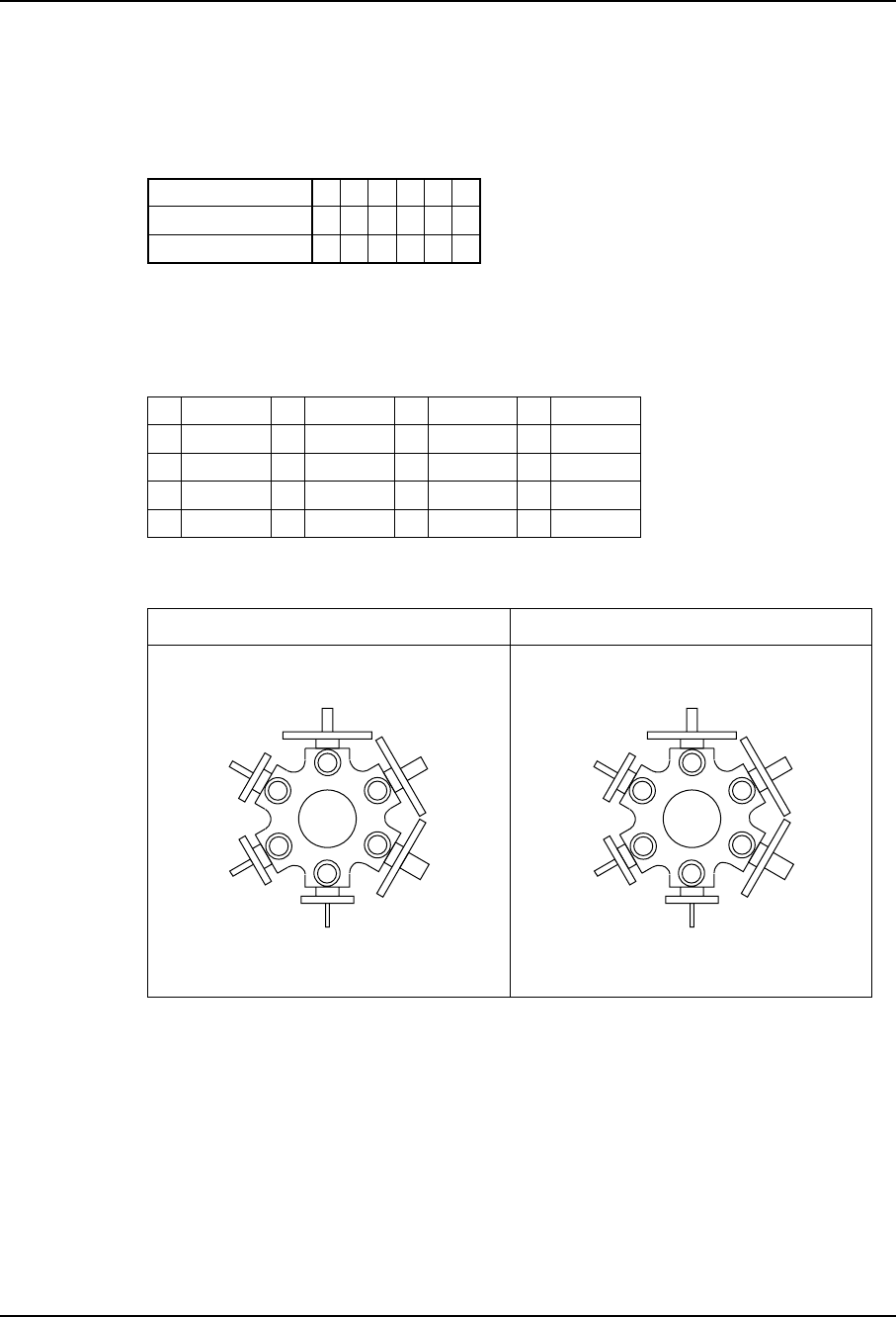
5.2 Nozzle Arrangement
The standard arrangement of nozzles is either type A or B, as shown below. Other
arrangements made up of nozzles A ~ O are possible.
The nozzle types listed here are identified in the following table.
Notes: (1) Only a nozzle with a ø20 reflective disk or smaller can be attached on either
side of a nozzle with a 20 mm square reflective plate.
(2) Only a nozzle with ø16 reflective disk or smaller can be attached on either
side of a nozzle with a 22 mm square or 22 square (black) reflective plate.
1
2
3
4
5
6
R12-007
R12-010
R12-013
R20-025
R20-037
S20-050
1
2
3
4
5
6
R12-010
R12-013
R12-018
R20-025
R20-037
S20-050
Type A
Nozzle Types
Type B
A
B
C
D
E
R12-007
R12-010
R12-013
M12-013
R12-018
F
G
H
I
J
K
R16-025
R16-037
R20-025
M20-025
R20-037
S20-050
S22-050
B22-050
S22-070
B22-070
L
M
N
O
Position on Head
Type A
Type B
Type A and Type B Nozzle Arrangements
1
A
B
2
B
C
3
C
E
4
H
H
5
J
J
6
K
K
– 12 – CP-642(E) Specifications
1.0
5. Nozzle