cp642规格书.pdf - 第20页
Notes: (1) Specify the camera type, narrow or wide view, in part data. (2) If a part larger than 3216 in size is inspected using the narrow view camera, the placing speed may be reduced. The narrow view camera is intende…
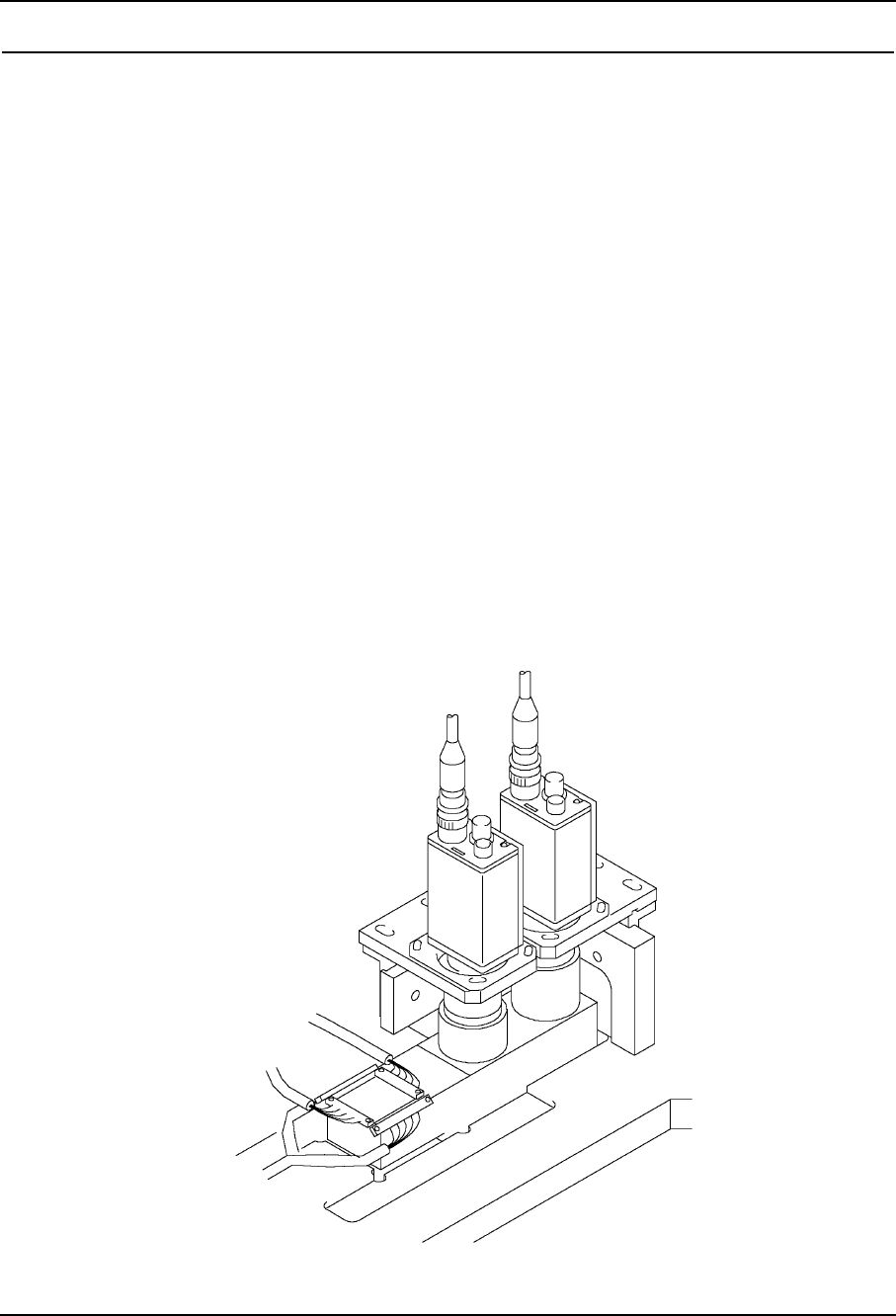
7. Vision System
7.1 Camera Unit (Parts Recognition)
The CP642/CP-642(E) is equipped with two cameras, each camera being adapted for
different uses; a high resolution small F.O.V. camera is used to acquire images of small
components such as 1005s and small SOTs, and a large F.O.V. camera is used for SOICs
and PLCCs. Also, frontlighting or backlighting can be selected according to the
configuration of the parts.
(1) Vision Controller
Attached inside the machine's base control box.
(2) Narrow View Camera
Part camera for backlight use
• 1005, 1608, 2125, 3216, SSMin, SMin, etc.
(3) Wide View Camera
The parts cameras can be switched from backlight to frontlight use. Frontlight use
is limited to J-lead parts.
• Backlight compatible parts: 19 x 20 mm maximum
• Frontlight compatible parts: 20 x 20 mm maximum J-lead parts
– 16 – CP-642(E) Specifications
1.0

Notes: (1) Specify the camera type, narrow or wide view, in part data.
(2) If a part larger than 3216 in size is inspected using the narrow view camera, the
placing speed may be reduced. The narrow view camera is intended for inspecting small
components at high resolution.
(3) If a part smaller than 4532 in size is inspected using the wide view camera, the placing
accuracy may be adversely affected. The wide view camera is designed for large components
from 4532 size parts to SQFP 48 pin devices.
7.2 Fiducial Mark Camera
(1) The camera is installed within the head assembly.
(2) The camera is used to accurately locate the board position by inspecting two or
more fiducial marks on the PCB. During operation, corrections are made to the part
placement position using this fiducial mark data.
– 17 – CP-642(E) Specifications
1.0
7. Vision System

8. Machine Control System
8.1 Machine Control Specifications
(1) Placement Position Data Entry • Absolute data
(2) Acceleration Control (XY-table) • UHi, Hi, Mid, Low, ULow:
5-level adjustable acceleration and
deceleration settings.
(3) Controllable Axes • Cam, X, Y, Z, D1, D2, Fθ, FRθ,
Nozzle changer: 9 axes
(4) CPU • 32 bit
(5) Maximum Number of Input Sequences • 5,000 sequences/board
(6) Maximum Number of Programs • 10 (1,500 sequences/program)
in Storage
(7) Memory • Battery backup (lithium battery)
(8) Data Input • F4G system
Note: Refer to 9.2.12, “F4G System”.
(9) Data Unit • 0.01 mm on X-, Y- and Z-axes.
• θ axis units : deg. and min.
(10) Communication • RS-232C
(11) Control Panel • Numerical keypad and function keys
(12) Vision Recognition Error Correction • Board displacement correction
• Part displacement correction
– 18 – CP-642(E) Specifications
1.0