cp642规格书.pdf - 第25页
9.2.10 Tri-color Signal Tower (1) Customer selectable green or blue lights with standard red and yellow lights. 9.2.11 HELPS Specifications (1) The HELPS system provides an in-line production system that supports automat…
9.2.2 Reference Pins
The following reference pins are available. Please specify the quantity and size
in your order.
• ø3.0 round or diamond shaped
• ø4.0 round or diamond shaped
9.2.3 Backup Pins
Order backup pins as needed
9.2.4 Vacuum Style Backup Pins
6 pins are used. Use of the vacuum backup pins increases board loading time by
one second compared to standard backup pins. However, this may vary
depending on the specified table mode.
Loading Speed Mode Time(sec)
Hi 5.0
Mid 5.5
Low 6.0
9.2.5 Additional Nozzles
Order additional nozzles as needed.
9.2.6 Part Supply Feeders
8, 12, 16, 24 and 32 mm feeders are available. Note requirements in your order.
9.2.7 Handy Terminal
(1) Permits the operator to conveniently enter and view data normally
displayed on the control CRT during device checks.
(2) Eliminate errors when replacing reels by allowing device checks via the
attached pen-type barcode reader.
9.2.8 Board-flow Direction
(1) Provides support for right to left board flow.
9.2.9 Roller-Guided Conveyor
(1) This unit enhances board transport performance by incorporating rollers
under the PCB transport conveyor belt.
(2) The maximum weight allowable is 1 to 2 kg including the transport pallet.
– 21 – CP-642(E) Specifications
2.0
9. Options

9.2.10 Tri-color Signal Tower
(1) Customer selectable green or blue lights with standard red and yellow
lights.
9.2.11 HELPS Specifications
(1) The HELPS system provides an in-line production system that supports
automatic changeover. The main features are as follows:
• Automatic changeover of production programs
• Automatic conveyor width adjustment
• Displays confirmation items and manual procedure instructions for
automatic changeover operation.
(2) The level of automation varies according to the customer's specification .
• Board type (barcode or pattern-code) trigger.
• Manual (operation SW) trigger
Note: When a barcode or pattern-code is used as a trigger, a separate unit to
read data at the previous stage is required. Details are available
separately.
9.2.12 F4G System
(1) The F4G system performs data communication with the machine using the
following:
• Computer (IBM PC compatible )
• C/C (communication center)
• Program modules (F4GO, F4GP, F4GM, etc. as required)
(2) Refer to the the separate “F4G Specifications” for details.
Note: The PC for the F4G system should be prepared by the customer prior to
the installation of the machine.
9.2.13 Other Requirements
(1) Any requirements not covered in these specifications may be discussed
separately.
(2) If you have any questions, please contact Fuji or one of our sales
representatives.
– 22 – CP-642(E) Specifications
1.0
9. Options
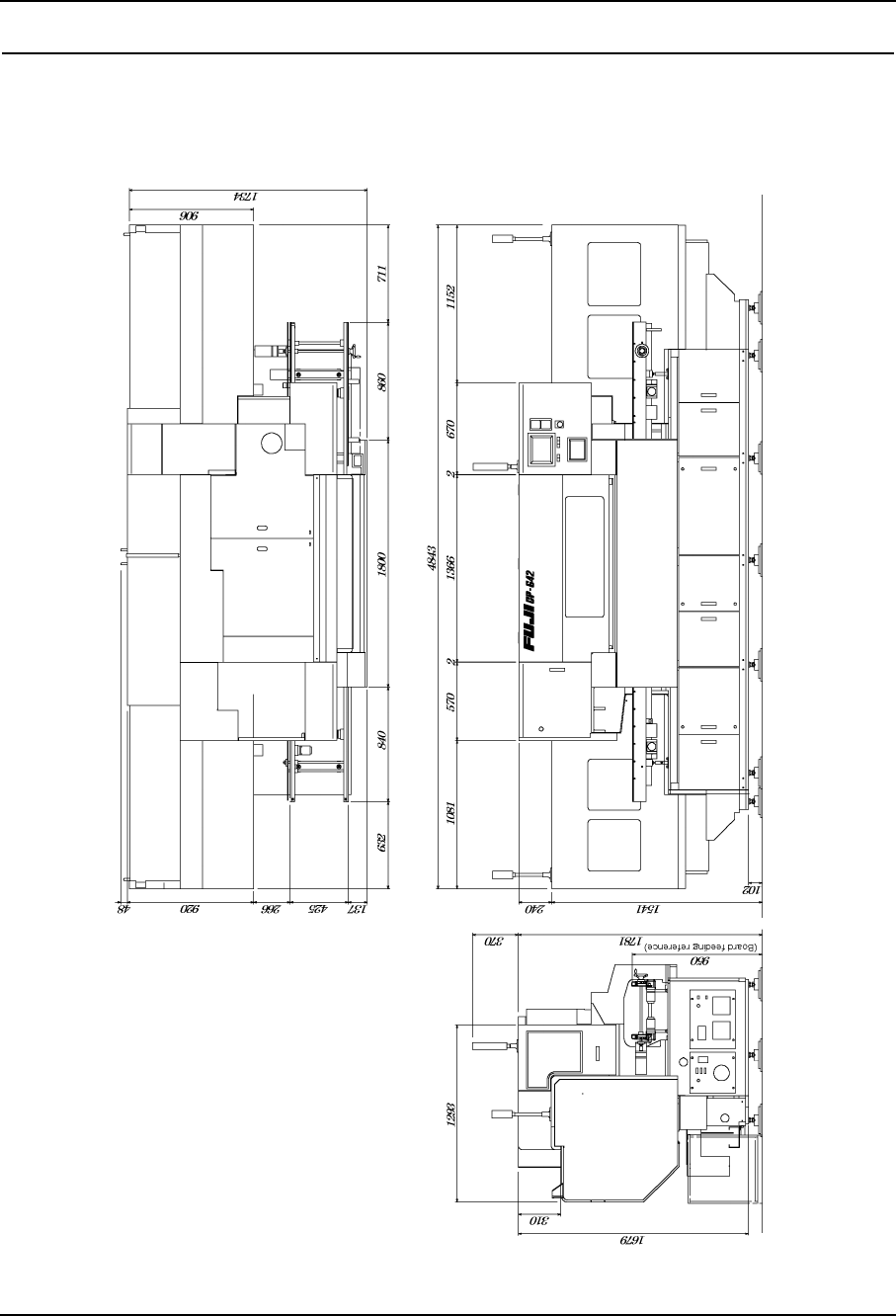
10. Equipment Overview
10.1 Exterior Schematic
10.1.1Models with Rear Cover
– 23 – CP-642(E) Specifications
2.0