Galaxy EX Squeegee Module.pdf - 第5页
SQUEEG EE MODULE OVERV IEW Ch apte r Issue 4, J un 18 Tech nical R efere nce Ma nual 10.5 NOTE Bot h la teral adjus ters are se t u p ‘ centred’ at the 1 1mm mark on th e microme ters. There is a maximum o f 4mm adjustme…
SQUEEGEE MODULE
OVERVIEW
10.4 Technical Reference Manual Chapter Issue 4, Jun 18
Lateral Squeegee
Adjust Mechanism
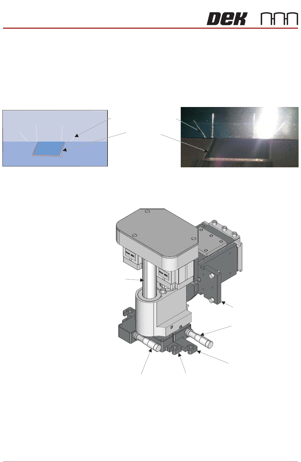
An option for printing on 3D stencils is the Lateral Squeegee Adjust
Mechanism. When printing 3D stencils, slit-edge squeegee blades are used,
front and rear. The printing edge of each squeegee blade has slits cut into it
that correspond to the raised surfaces of the stencil. As the squeegee
traverses the image, the slits rise up over the leading edge (or fall into the
recesses) of the stencil’s surface features.
Figure 10-2 Slit Edged Squeegee (depicting mis-alignment)
With the squeegee blades fitted (not shown above) they can be adjusted in the
X direction using the front and rear lateral adjusters (micrometer scales).
Stencil Step
Slitted Squeegee Blade
Squeegee Placed Above the Stencil Step
Diagramatic Representation
Squeegee Mechanism (squeegees not shown)
Squeegee Mechanism
Squeegee Mount (Rear)
Squeegee Mount (Front)
Lateral Adjuster (Rear)
Lateral Adjuster (Front)
Front Drive Shaft
SQUEEGEE MODULE
OVERVIEW
Chapter Issue 4, Jun 18 Technical Reference Manual 10.5
NOTE
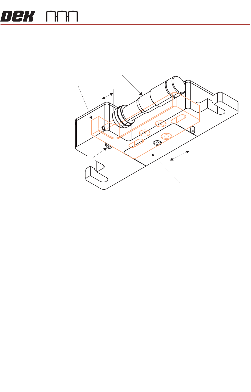
Both lateral adjusters are set up ‘centred’ at the 11mm mark on the
micrometers. There is a maximum of 4mm adjustment either side of this
setting.
Figure 10-3 Front Squeegee Mount (viewed from underneath)
Internally, an adjuster block is attached to each drive shaft of the squeegee
mechanism.
The micrometer centre position is preset, by the user, this centralises the
movement of the lateral squeegee mount in the X direction.
Two slots in the adjuster block allow a total of 8mm of movement; the lateral
squeegee mount is locked in position with two cap headed screws located in
the top of the block. By slackening off these screws, up to 4mm of adjustment
either side of centre can be achieved. A return spring facilitates adjustment in
both directions.
At product changeover, the squeegee blade positions need to be adjusted to
suit the new product alignment.
Lateral Squeegee Mount
4mm
+
-
Adjust Micrometer
Internal Adjuster Block
11mm
Return Spring
SQUEEGEE MODULE
ELECTRICAL SCHEMATIC
10.6 Technical Reference Manual Chapter Issue 4, Jun 18
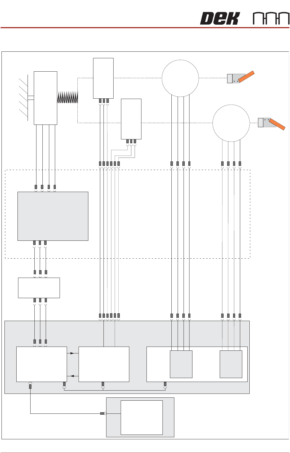
ELECTRICAL SCHEMATIC
Squeegee
Front
Home
(9SE04)
Squeegee
Rear
Home
(9SE05)
Rear
Squeegee
Stepper
Motor
(9M4)
Motor 1 B-
Motor 1 B+
Motor 1A-
Motor 1A+
Motor 2 B-
Motor 2 B+
Motor 2A-
Motor 2A+
Print Carriage
9PL16
9PL08
9PL17
0V
+V
-IN
+IN
Strain Gauge Bridge
(9SE6)
Spring Beam
9SK11
9SK12
Print Carriage I/O
Node 3
N3PL16
M36PL35
N3SK2
N6PL3
CAN BUS
PC
Motherboard
M36PL35
USB
M36Pl28
NextMove ES
(I/O Node 1)
NextMove
Interface
Dual Stepper
Card X2
M36 Machine Control
Step 3
Step 4
Front
Squeegee
Stepper
Motor
(9M3)
M36PL21
M36PL12
M36PL21
CAN
In
Rising
Table
Node 6
N6SK2