SIPLACE D系列Servicemanual.pdf - 第102页
Service Wo rk Placement Heads White Balance Process for SIPLACE Digital Vision Camera 102 Servicemanual (internal ve rsion) SIPLACE D Series 4.2.3.5 Continuation X Once the calibration process has been completed, the tec…
Service Work
White Balance Process for SIPLACE Digital Vision Camera Placement Heads
Servicemanual (internal version) SIPLACE D Series
101
4.2.3.4 The Illumination Calibration Process
X The PCB camera is positioned to check the presence of the calibration tools. Fiducial recognition
determines whether all the calibration tools are present.
X The PCB camera centers the 3 fiducials for
position recognition of the calibration tool
carrier.
X Illumination calibration is now performed for
the PCB camera.
(see diagram of standard PCB camera)
X Tray position recognition is performed again.
X The gantry placement head picks up its
appropriate calibration tool for the component
camera.
X The calibration tool is placed under or above
the respective component camera, the
balance process is performed and the
calibration tool is returned to where it was
picked up from.
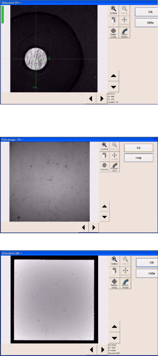
(Here you can see a video image of the C&P6
component camera.
X The calibration process is repeated for the
cameras of the second gantry in the
placement area or for the second placement
head of the gantry.
Service Work
Placement Heads White Balance Process for SIPLACE Digital Vision Camera
102 Servicemanual (internal version) SIPLACE D Series
4.2.3.5 Continuation
X Once the calibration process has been completed, the technician needs to confirm this and then
have the carrier transported through to the output conveyor.
X When exiting SITEST, a message will be issued, informing you that machine data still need to be
saved. If you confirm this message, the values determined will be written to the camera EPROM.
X For report purposes, an XML file is created for each camera, in the
C:\SR-Daten\FCCS
folder.
This file is assigned a time stamp in its file name.
X In an ideal case, this file should be created before starting calibration.
However, the technician currently needs (SR/MC 603/604) to manually create these files in the
individual camera menus and select the respective storage paths (e.g.
C:\SR-Daten\FCCS
).
X From SR/MC SW version 605, the respective EPROM data is saved before and after the white
balance process, in a file in the
C:\SRDaten\FCCS
folder.
The file name contains the following:
- gantry name
- camera type name
- before/after calibration
- date stamp
Example:
Gantry_1_CameraID_25_after_FCCS_2008_06_06_14_01_28.xml
The illumination tool carrier is moved into
placement area 2 and the calibration process is
repeated, according to the machine configuration.
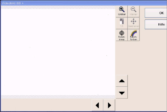
Here you can see a diagram of the FLIP-CHIP
camera option for the TWIN/P&P head.

Service Work
White Balance Process for SIPLACE Digital Vision Camera Placement Heads
Servicemanual (internal version) SIPLACE D Series
103
4.2.3.6 Error States, Messages and Assessments
Handling errors:
If the white balance tool for the PCB camera is inserted the wrong way round, this software version (SR/
MC 603/604) will issue an internal system error.
If one of the C&P12/6/TWIN camera white balance tools is inserted incorrectly, a PCB camera fiducial
error will be issued.
For assessment of the FCCS results, observe the following:
All installed illumination levels should have similar basic illumination values. Illumination levels with high
deviations are an indication of damage to the LEDs or their control systems.
If you obtain illumination values exceeding 400, the customer should be advised to send the camera to
SIEMENS for maintenance.
If results of around 800 are obtained, the camera will no longer function. The FCCS software will issue
the relevant error message and will terminate the measurement.
Excerpt from the
FCCS…xml file
:
an evaluation for a FCCS protocol XML file report is in progress.
…. />
<Illumination ‘brightness values’ for the illumination levels, multiplied with the ‘Camera
gain’ value after the white balance process
Plane1 ="123" Basic brightness values for the individual camera-specific illumination levels
–-
Plane2 ="126" The values divided by the Camera Gain factor are typically under one
hundred.
Plane3 ="117"
Plane4 ="140"
Plane5 ="129"
Plane6 ="0" This level is not available for this camera type.
CameraGain ="2.925" Camera amplification factor
DeadTime ="48800" />