SIPLACE D系列Servicemanual.pdf - 第67页
Service Work D3 Gantry Servicemanual (internal version) SIPLACE D Series 67 4.1.3.7 Replacing the X Axis Incremen tal Encoder [03020588S-xx] Overview Press-fit connections Removal Legend 1. Installation point for head in…
Service Work
Gantry D3
66 Servicemanual (internal version) SIPLACE D Series
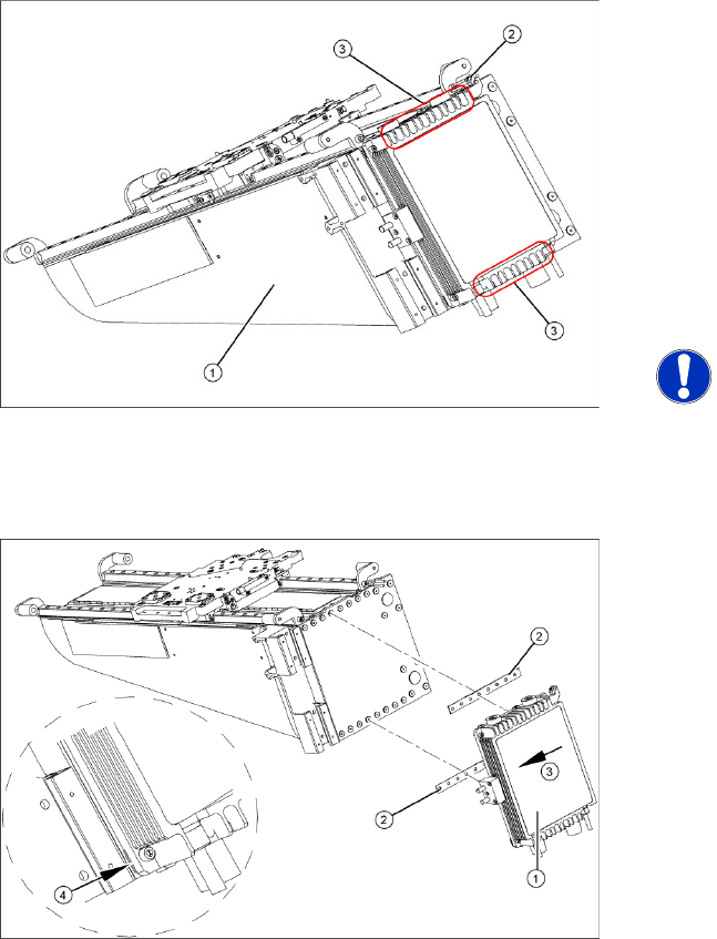
4.1.3.6 Replacing the Y Linear Motor - Primary Part
Item number
Linear motor Y drive, complete (D3, X series) [03013459-xx]
Removal
Installation
Settings
X Check the axis dynamics of the drives removed.
X Dismantle the gantry (see section (4.1.3.5 Re-
placing Gantries
J
61 ) ) and put it in a
suitable place (1).
X Remove the cable ties holding the connection
cable.
X Remove the proximity switch mount (2) and
proximity switches.
X Undo the 16 fastening screws (3). Make sure
you do not lose the insulating plates
underneath the screws. These must be
replaced after completing service work.
NOTE:
The fastening screws have been
secured with locking varnish (Loctite
241).
X Loosely fasten the new Y drive (1) with the
screws and insulating plates (2) provided. Use
Loctite 241 to secure it.
X Press the motor upwards, within the tolerance
of the drilling (3). if you do not do this, the
motor could lie on the bottom guides. Now
tighten the two center screws.
X Make sure that the ends of the insulation
plates (4) are not protruding (these plates are
not symmetrically centered). If necessary,
press these back in with a suitable tool (e.g.
screwdriver).
X Then tighten all 16 fastening screws with the
aid of a torque wrench (first in the center, then
at the top and lastly at the bottom) (5.5 N).
X Install the proximity switch mount and
proximity switches.
X Fasten the connection cable so that it will not
be in the way when installing the gantry.
X Install the gantry and the trailing cable.
Service Work
D3 Gantry
Servicemanual (internal version) SIPLACE D Series
67
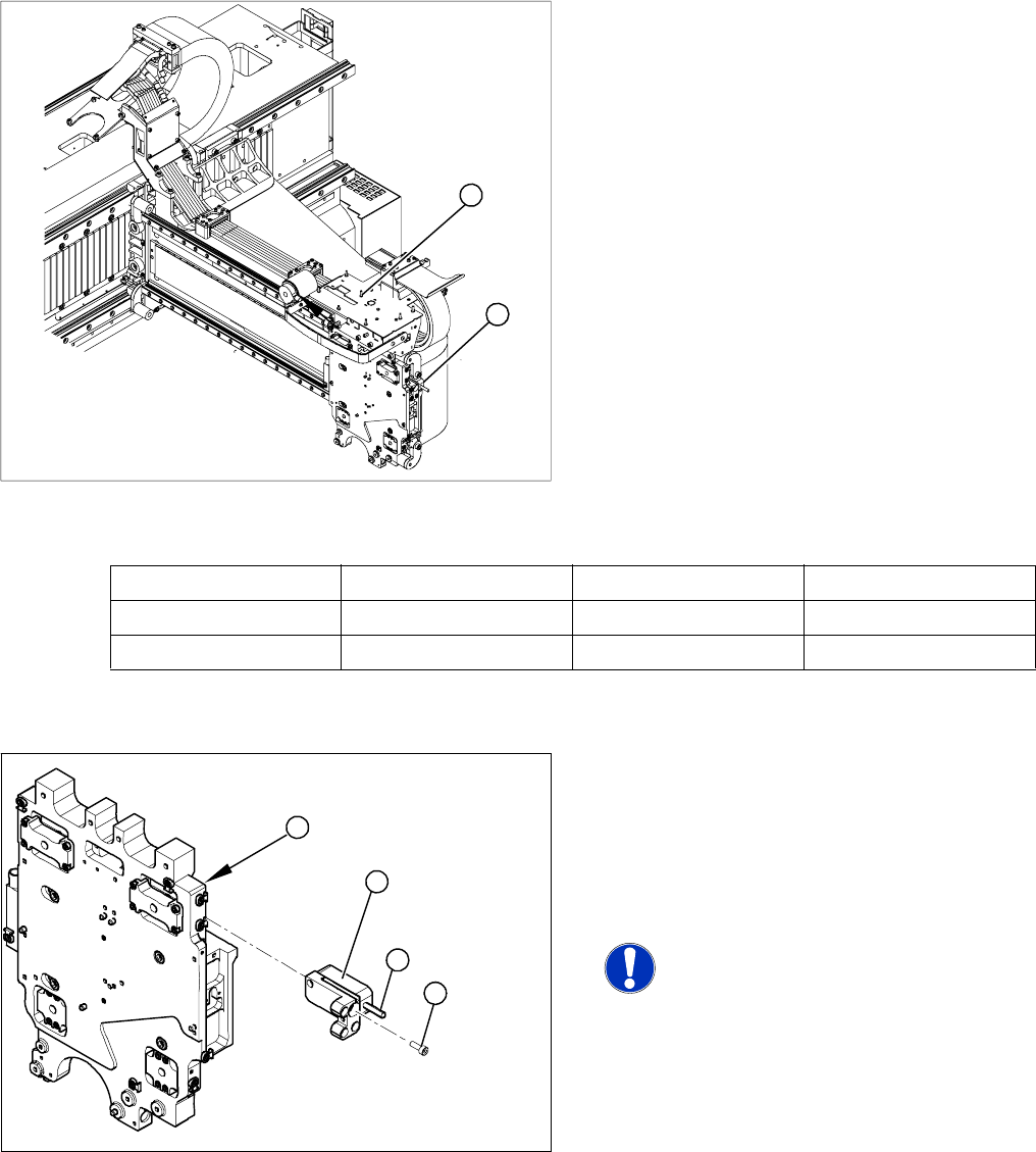
4.1.3.7 Replacing the X Axis Incremental Encoder [03020588S-xx]
Overview
Press-fit connections
Removal
Legend
1. Installation point for head interface and Vision
board
2. Incremental encoder position
X Unplug the incremental encoder press-fit
connection (2) from the head interface (1).
1
2
Assembly Gantry Board Terminals
X axis incremental encoder Gantry 1 (C&P head ) Head interface 03000901 X15ac
X axis incremental encoder Gantry 2 (Twin Head) Head interface 03000901 X15bc
Legend
1. Head plate - front view
2. Incremental encoder
3. 3 x fastening screws
4. Grub screw (secured with Loctite No. 241)
NOTE: Grub screw on the
incremental encoder
If the incremental encoder is installed
on the head plate of a CFK 04 or 06
gantry, the grub screw is without
function. Do not loosen or tighten this
grub screw.
X Unthread the connection cable as far as the
incremental encoder (2).
X Loosen the three screws (3) fastening the
incremental encoder (2) of the X axis and
carefully lift off the incremental encoder.
3
4
1
2
Service Work
Gantry D3
68 Servicemanual (internal version) SIPLACE D Series
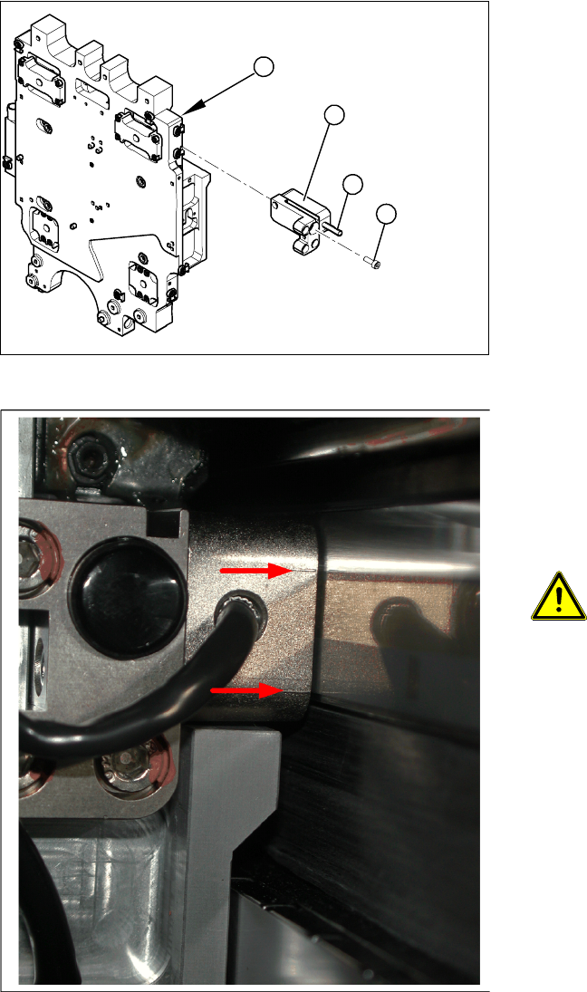
Installation
X Clean the reading surface of the incremental
encoder with a cloth and ethanol or with a
cleansing tip.
X Loosely fasten the incremental encoder (2)
with three fastening screws (3).
X The incremental encoder must be aligned with
a 0.4 mm gap to the scale. Use the
corresponding thickness gauge (plastic).
3
4
1
2
4-17: Casting marks on the incremental encoder
X You must set the exact height to the scale.
X Align the incremental encoder, using the two
casting marks (arrows), which mark the read
area.
X Tighten the fastening screws.
X Reconnect to the electricity supply.
ATTENTION: Check how the cables
are run!
Make sure that the axes can be moved
without damaging the cables.
X Fasten them with cable ties.
X Move the gantry into the end stopper and
check that the buffer does not come into
contact with the cable.