SIPLACE D系列Servicemanual.pdf - 第90页
Service Wo rk Placement Heads Replacing the Raceway (Circular Arc Guide) 90 Servicemanual (internal ve rsion) SIPLACE D Series 4.2 Placement Heads 4.2.1 Replacing the Raceway (Circular Arc Guide) Tools Removal X Remove t…
Service Work
D4 Gantry
Servicemanual (internal version) SIPLACE D Series
89
Settings
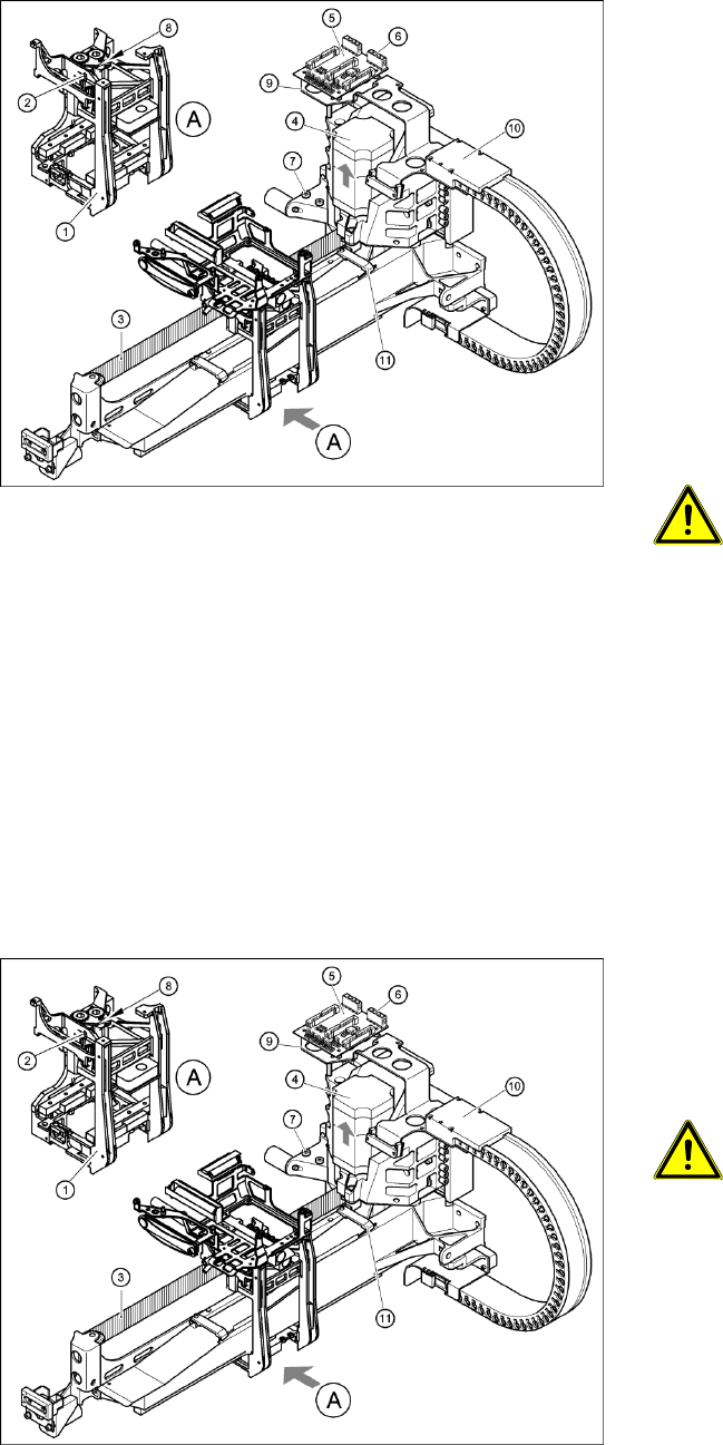
4-28: Replacing the X-axis motor unit
Gantry 2 or 4
X Carefully insert the X motor unit (4) as far as
the stop, making sure that you do not damage
the toothed belt. The motor cable points
towards the permanent magnets of the linear
drive.
X Fix the X motor unit into place with the two
hexagon socket-head screws (7).
X Fit the cable holders for the trailing cable (10).
X Fit the board holder (9).
X Plug the X motor plug into its socket on the X/
Y distributor (5).
X Fix the flat ribbon cable with the cable clamp
(11).
X Fix all the cables with cable ties.
CAUTION:
Make sure that the cables are firmly
seated. Otherwise, the high
acceleration forces may cause the
cable to slip out of position and shear
through.
X Tension the X toothed belt with the hexagon
socket-head screw (2).
X Use the three M6 x 8 hexagon socket-head
screws to fit the black cover strip to the
crossbeam above the gantry concerned.
X Connect the cable of the fan motor to the
socket.
4-29: Replacing the X-axis motor unit
X Push the head mount (1) towards the X axis
motor unit, as far as the stop on the
elastomeric spring.
X Turn the hexagon socket-head screw (2) to set
the belt tension to 53 Hz + 1/-3 Hz.
CAUTION:
Do not overstretch the toothed belt
when adjusting the belt tension.
X Secure the hexagon socket-head screw (2)
with the locknut (8).
Service Work
Placement Heads Replacing the Raceway (Circular Arc Guide)
90 Servicemanual (internal version) SIPLACE D Series
4.2 Placement Heads
4.2.1 Replacing the Raceway (Circular Arc Guide)
Tools
Removal
X Remove the star from the head. (See section "Replacing the Star" in the Service Manual.)
Legend
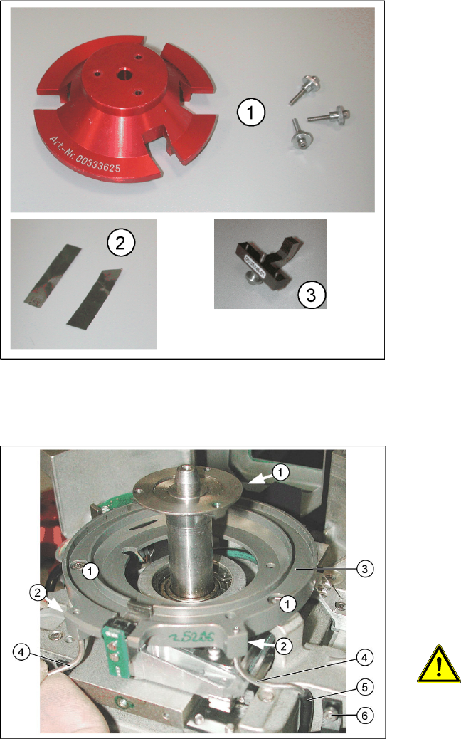
1. Gauge for raceway [00333625-xx] with 3
fastening screws
2. 2 x 0.01 mm feeler gauge
3. If the Z axis has been removed, you will also
need a gauge for the Z axis mechanics
[00335346-xx].
Feeler gauge, 0.7 mm
Allen key, 0.71 mm to 3.5 mm
Retrofitting set for circular arc guide
[00334847-xx]
X Loosen the two hose holders (6) for the air
blast supply and pull the hoses (5) on the left
and right off the metal tube (4) for the air blast
supply.
X Loosen the 3 screws (1) fastening the raceway
(3) and carefully lift the raceway off the front of
the head.
X Loosen the grub screws (2) for the air blast
supply tubes (4) and carefully remove these
tubes.
ATTENTION:
Take care not to bend the tubes (4).
Service Work
Replacing the Raceway (Circular Arc Guide) Placement Heads
Servicemanual (internal version) SIPLACE D Series
91
Installation
X Insert the tubes into the new raceway but do
not yet tighten the grub screws which fasten
these tubes.
ATTENTION:
Take care not to bend the tubes.
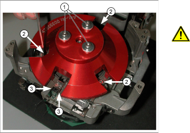
X Fit the raceway onto the front of the head.
X Fit the raceway gauge onto the motor axis, as
shown in the diagram. Tighten the gauge with
the three screws (1) provided, so that you can
reach all the screws (2) for the raceway and
the Z axis.
X Fit the 0.01 mm feeler gauges (3) on both side
of the Z axis (or the Z axis mechanics gauge).
X Fasten the circular arc guide with the three
screws (2).
X Dismantle the gauge for the raceway.
X Remove the feeler gauges and test the Z axis
for ease of movement.
X With the help of the feeler gauge, adjust the
metal tubes for the air kiss supply to 0.7 mm
higher than the circular arc guide and fix into
place with the grub screws (Allen key,
0.71 mm).
X Attach the silicon hose to the metal tubes and
fix this to the housing with the hose holders.
X Fit the star back into the head. (See section
"Replacing the Star" in the Service Manual.)
Set the zero position with the power pack and
determine the zero point correction value.