SIPLACE D系列Servicemanual.pdf - 第37页
Service Work D1/D2 Gantry Servicemanual (internal version) SIPLACE D Series 37 4.1.2.5 Replacing the X Motor Unit [00333167 -xx] Tools and Equipment Set of DIN 911 Allen keys Cable ties Belt tension measuring devic…
Service Work
Gantry D1/D2
36 Servicemanual (internal version) SIPLACE D Series
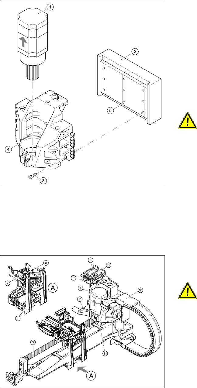
Installing the primary part of the linear motor
Settings
4-12: Replacing the linear motor primary part (D4)
X Fit scotch tape to the lower edge of the primary
part of the linear motor, so that the lockrails (5)
do not fall out during assembly.
X Push in the primary part from the side.
X Fasten the primary part (2) with the nine M5 x
20 hexagon socket-head screws (3) to the
motor bracket (4).
X Make sure that the primary part is aligned in
parallel to the permanent magnet.
X Fit the X axis motor unit as described in sec-
tion (4.1.2.5 Replacing the X Motor Unit
[00333167-xx]
J
37 ) .
X Fix all the cables with cable ties.
CAUTION:
X Make sure that the cables are firmly
seated. Otherwise, the high
acceleration forces may cause the
cable to slip out of position and shear
through.
X Fit the permanent magnets (4 or 16 M6 x 12
hexagon socket-head screws). The space at
the bottom must be 0.8 mm. Use the
appropriate feeler gauge or plastic strip to help
you. A gap of approx. 0.8 mm should be
between the magnet plates.
X Fit the cover strips on the crossbeam above
the gantry concerned (3 M6 x 8 hexagon
socket-head screws).
4-13: Replacing the X-axis motor unit (D4)
X Use the belt tension measuring device to set
the X-axis toothed belt tension to 44 Hz + /-1
Hz.
CAUTION:
X Do not overstretch the toothed belt
when adjusting the belt tension.
X Secure the M4x35 hexagon socket-head
screw (2) with the locknut (8).
X Check the axis dynamics of the drives
removed.
Service Work
D1/D2 Gantry
Servicemanual (internal version) SIPLACE D Series
37
4.1.2.5 Replacing the X Motor Unit [00333167-xx]
Tools and Equipment
Set of DIN 911 Allen keys
Cable ties
Belt tension measuring device TSM [00326015-xx]
"Measuring belt tensions" operating instructions
Parts
X motor unit [00333167-xx]
For SIPLACE D1 machines: Retrofitting guide for X axis heat sink [00195618-xx]
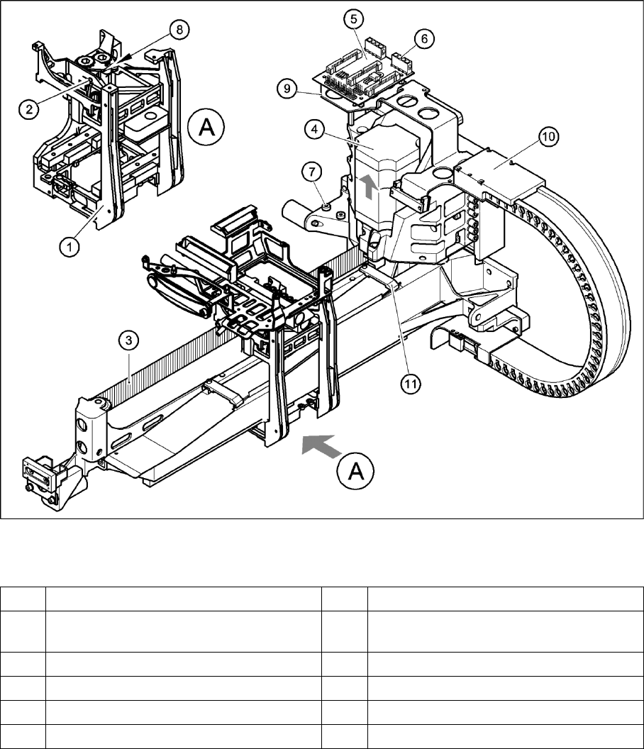
Removing the X-axis motor unit
4-14: Replacing the X motor unit (D4 shown as example)
Legend
1 Head mount 7 2 x M6 x 14 hexagon socket-head screws
2 M4 x 35 hexagon socket-head screw for
tensioning the X-axis toothed belt
8 Locknut
3 Synchroflex X-axis toothed belt 9 Board holder
4 X-axis motor unit 10 Cable clamps
5 X/Y distributor 11 Cable clamp
6 X5 socket for X-axis motor

Service Work
Gantry D1/D2
38 Servicemanual (internal version) SIPLACE D Series
X Switch off the machine and secure it to prevent unauthorized reactivation.
1 gantry D1 (2 gantries D2)
X Remove the cover strip on the crossbeam above the gantry concerned:
Unplug the fan cable. The fan is fixed to the cover strip.
Remove the cover strip (3 M6x8 hexagon socket-head screws).
X Cut the cable ties holding the X-axis motor cable.
X Remove the cable clamp for the flat ribbon cable (11).
X Disconnect all the plugs from the X/Y distributor (5).
X Remove the X/Y distributor (5).
X Remove the board holder for the X/Y distributor (9).
X Remove the cable holders (10) on the trailing cable.
X To relax the toothed belt (3), proceed as follows:
Loosen the locknut (8) and
Turn the hexagon socket-head screw (2) counterclockwise.
X Loosen the two M6 x 14 hexagon socket-head screws (7) fixing the X motor unit (4).
X Pull the X motor unit (4) up and out,
X at the same time pushing the board holder slightly to the side.
DANGER: POWERFUL MAGNETIC FIELD
X Always follow the special safety instructions when working in the vicinity of powerful magnetic
fields.