SIPLACE D系列Servicemanual.pdf - 第52页
Service Wo rk Gantry D3 52 Servicemanual (internal ve rsion) SIPLACE D Series Shortening the Y hoses to the pneumatic distributor in the machine base 1. Gauge for sh ortening the hoses 2. Stopper edge at the machine base…
Service Work
D3 Gantry
Servicemanual (internal version) SIPLACE D Series
51
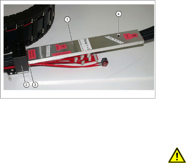
Shortening X hoses at the X trailing cable
clamp (to the pneumatic distributor at the
head mount)
1. Gauge for shortening the hoses
2. X trailing cable clamp
3. Stopper edge (gauge at clamp)
4. Hose marking
X Observe the designation for the respective
gantry on the gauge (1) (gantry 1+3 or gantry
2+4). Select the correct gauge.
X Place the stopper edge (3) of the gauge (see
mark labeled edge for clamp X+ Y on the
gauge) at the edge of the clamping plate (2) for
the X trailing cable.
X Mark the pneumatic hoses through the holes
(4) in the gauge. Observe the position labeled
X hose.
ATTENTION:
Mark the correct position!
X Observe the position labeled X hose.
X Observe the position marked
machine inside on the gauge.
X To ensure that they have the correct
length, cut the pneumatic hoses at
the marking labeled "X hose". If the
pneumatic hoses are cut too short,
you will have to discard the entire
trailing cable.
X Use the hose pliers to cut the pneumatic hoses
at the marked position. The pneumatic hoses
can now be run inside the pneumatic
distributor, with the correct curvature.
Service Work
Gantry D3
52 Servicemanual (internal version) SIPLACE D Series
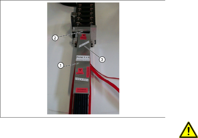
Shortening the Y hoses to the pneumatic
distributor in the machine base
1. Gauge for shortening the hoses
2. Stopper edge at the machine base clamp
3. Hose marking
X Observe the designation for the respective
gantry on the gauge (1) (gantry 1+3 or gantry
2+4). Select the correct gauge.
X Place the stopper edge (2) of the gauge (see
mark labeled edge for clamp X +Y on the
gauge) at the edge of the clamp for the Y axis.
X Mark the pneumatic hoses through the holes
(3) in the gauge.
ATTENTION:
Mark the correct position!
X Observe the position labeled Y
hose.
X To ensure that they have the correct
length, cut the pneumatic hoses at
the marking labeled "Y hose". If the
pneumatic hoses are cut too short,
you will have to discard the entire
trailing cable.
X Use the hose pliers to cut the pneumatic hoses
at the marked position. The pneumatic hoses
should now have the correct length and can be
connected to the severed pneumatic hoses in
the machine base.
Service Work
D3 Gantry
Servicemanual (internal version) SIPLACE D Series
53
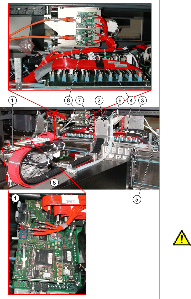
Overview
Version 1 from B-079
Legend
1. Head board with digital Vision board assembly
[03017836-xx]
2. Trailing cable console
3. Power track chain
4. Trailing unit interface gantry
5. Pneumatic hoses to the pneumatic distributor
(in the machine base)
6. Gantry distributor
7. Gantry interface
8. Hotlink filter [03010670-xx]
9. Connection piece for cooling tubes to Y motor
X The flat ribbon cable and the camera cable are
run from the head board (1) via the trailing
cable console (2) and the power track chain (3)
to the gantry interface (7) and the trailing cable
interface gantry (4). The camera cable ends at
the hotlink board (8).
X The pneumatic hoses are fed from the
pneumatic distributor (6), via the trailing cable
console (2) and the power track chain (3) to
the gantry distributor in the machine base.
X Disconnect the camera cable from the hotlink
board (8).
X Remove cable ties where necessary.
ATTENTION:
Note the order in which the terminal
connections are arranged.
X Label the press-fit connections to the
flat ribbon cable and the camera
cable, for easier reconnection later.
X Disconnect the Y motor cooling tubes at the
connection pieces (9).