SIPLACE D系列Servicemanual.pdf - 第47页
Service Work D3 Gantry Servicemanual (internal version) SIPLACE D Series 47 Installation check Settings X Check the axis dynamics of the dr ives removed. X Move the gantry back and forth . Make sure the gantry does not r…
Service Work
Gantry D3
46 Servicemanual (internal version) SIPLACE D Series
Installation
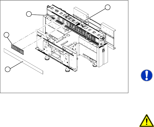
X Carefully rub the contact surfaces (1) of the
magnet with a dressing stone (oil stone) and
wipe clean with a cloth and ethanol.
X Install the magnetic strip (2). Make sure that
there is a gap of 0.8 mm between the
individual magnetic strips.
X Tighten the screws to a torque of 9.5 N.
X Check the blue cover for damage and replace
if necessary.
X Attach the blue cover to the fastening screws.
NOTE:
Production tolerance could mean that
the cover will not lock into place. In this
case, sand off a little of the cover upper
edge.
X Knock the cover into place with a rubber mallet
and block of wood.
CAUTION: Take care that the cover
and the magnetic strip are correctly
positioned!
The cover must be sit lower than the
magnetic strip.
X Move the gantry to one side.
X Hook the notch of the magnet cover plate (3)
approximately in the center (4).
X Move the gantry over the magnet cover.
X Pull the magnet cover with the aid of a second
strong person on both sides and hook in at
both ends.
X The magnet cover must lie flat on the magnets.
You should not see any unevenness e.g.
buckling, waves.
4
1
3
2
Service Work
D3 Gantry
Servicemanual (internal version) SIPLACE D Series
47
Installation check
Settings
X Check the axis dynamics of the drives removed.
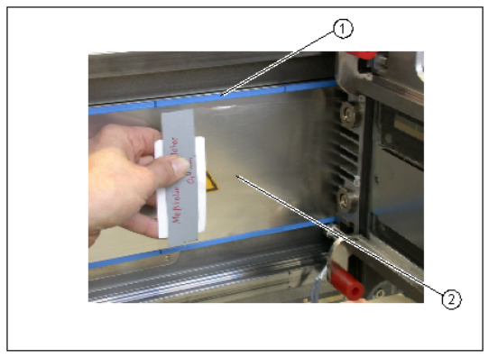
X Move the gantry back and forth. Make sure the
gantry does not rub against the magnet cover
or the blue covers (1).
X Check the 0.4 mm gap between the Y axis
drive and the magnet cover.
X To do this, place the thickness gauge (2)
between the Y axis drive and the magnet cover
and then push the gantry back and forth.
Make sure none of the parts jam or rub.
X Repeat this process with a 0.5 mm thickness
gauge. In this case, the gantry may rub against
the warning label.
X Clean the magnet cover with a cloth and
ethanol.
X If the gap is not large enough, you will need to
remove the magnet cover and clean
everything again.
Remove the magnetic strip and clean the
contact surface
Check the blue cover
Service Work
Gantry D3
48 Servicemanual (internal version) SIPLACE D Series
4.1.3.4 Replacing the Trailing Cable (IGUS) for D3/X4I/X Series from B-079 [03021065-xx]
Handling the Hose Unlocking Tool [03047090-xx]
Introduction
Parts
For SIPLACE X series machines with serial numbers from B-079 (version 1):
– Trailing cable, digital 1P - for placement area (PA) with 1 gantry: [03022236S01]
– Trailing cable, digital 2P U - for PA with 2 gantries, gantry 3 or 1: [03022237S01]
– Trailing cable, digital 2P G - for PA with 2 gantries, gantry 2 or 4: [03021065S01]
For SIPLACE X series machines with serial numbers after B-079 (version 2):
– Trailing cable, digital 1P - for placement area (PA) with 1 gantry: [03050655Sxx]
– Trailing cable, digital 2P U - for PA with 2 gantries, gantry 3 or 1: [03050817Sxx]
– Trailing cable, digital 2P G - for PA with 2 gantries, gantry 2 or 4: [03050934Sxx]
For SIPLACE X4I machines:
– Trailing cable, digital 2P U - for PA with 2 gantries, gantry 3 or 1: [03050817Sxx]
– Trailing cable, SIPLACE X4i l 2P G - for PA 03051596-0, gantry 2 or 4: [03051596Sxx]
Hose pliers for cutting the pneumatic hose
Hose unlocking tool [03047090-xx]
Pipe/hose cutters [0038144301]
Retrofitting guide for vacuum pump - if required - [0019508901]:
Locking varnish Loctite 241 [0210103701]
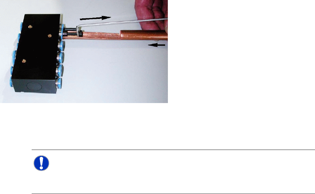
Due to the poor access to the pneumatic
distributor, we recommend using an unlocking
tool.
With the help of the hose unlocking tool
[03047090-xx] you can open the unlocking ring
(blue here) for the compressed air connection.
This enables you to remove both the hoses and
the dummy plugs (additional tool included in set).
X Use the pipe-shaped tool (1) to open the
unlocking ring.
X Carefully pull the hose out of the compressed
air connection. The diagram shows the
removal of a dummy plug (2), not a hose.
NOTE: Old and new trailing cables
If the old trailing cable is replaced with a new trailing cable version, you will also need to replace
the hotlink card and the Vision board spread spectrum. These are not included in the spare parts
sets and need to be ordered separately!
The new trailing cable is installed after machine serial number B-79 as version 2.