SIPLACE D系列Servicemanual.pdf - 第80页
Service Wo rk Gantry D4 80 Servicemanual (internal ve rsion) SIPLACE D Series 4.1.4.3 Replacing th e Y Linear Motor - Secondary Part Tools and Equipment Set of DIN 911 Allen keys SITEST program Parts Magnetic strip…
Service Work
D4 Gantry
Servicemanual (internal version) SIPLACE D Series
79
Switch the adhesive device over to the right-hand side of the gantries.
X Extract the long pin from the adhesive device.
X Lift the adhesive device off the Y ball bearing unit guide rail.
X Move both basic gantries as far as possible to the left.
X Place the adhesive device in the same position as it was before.
X Fit the adhesive device again as described above and continue with the fixture process.
X Remove the right guide and the rest of the protective sheet.
X Push the adhesive device as far as the right stop.
X Remove the adhesive device.
X Press the rest of the scale down with your hand and with the help of a tear-resistant cloth.
X Remove the centering pin from the left side of the scale.
X Clean the scale with a cloth and ethanol.
X Clean the reading surface of both Y incremental encoders with a cloth and ethanol.
Settings
X Check the track signals at the two incremental encoders.
X Calibrate the Y zero point correction values at the two gantries.
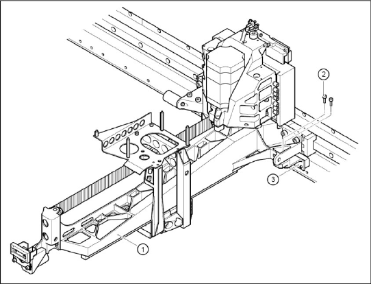
X Loosely screw the two Y incremental encoders
(3) to the basic gantry with two M3x10
hexagon sprocket-head screws (2), each.
X Use the feeler gauge to set the 0.4 mm gap
between the Y incremental encoder and scale
and then tighten the fastening screws.

Service Work
Gantry D4
80 Servicemanual (internal version) SIPLACE D Series
4.1.4.3 Replacing the Y Linear Motor - Secondary Part
Tools and Equipment
Set of DIN 911 Allen keys
SITEST program
Parts
Magnetic strips - secondary part of Y drive
Removal
X Switch off the machine and secure it to prevent unauthorized reactivation.
X Move the gantry in the PCB transport direction and position it so that the permanent magnets can be
removed:
Gantry 1 via the permanent magnets (1C)
Gantry 2 via the permanent magnets (2C)
Gantry 3 via the permanent magnets (2C)
Gantry 4 via the permanent magnets (1C)
X Remove the black cover strips on the crossbeam above the gantry concerned (3 M6 x 8 hexagon
socket-head screws).
DANGER: POWERFUL MAGNETIC FIELD
Always follow the special safety instructions when working in the vicinity of powerful magnetic
fields.
Service Work
D4 Gantry
Servicemanual (internal version) SIPLACE D Series
81
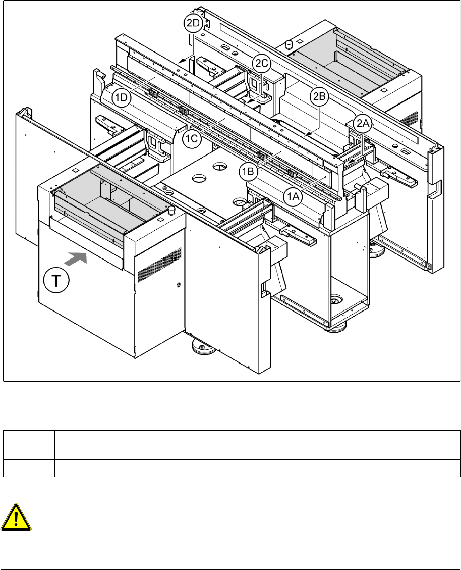
4-21: Position of the permanent magnets for the Y-axis linear drives
Legend
X Remove the permanent magnets from the gantry concerned:
X Remove the magnet cover plate as follows:
Lift both sides of the cover plate at the same time.
Pull it out towards one side, until it reaches the gantry.
Insert the notch of the shorter end into the groove between the magnetic strips.
Move the gantry over this groove, until the cover plate can be removed.
X Carefully remove the blue covers e.g. with a screwdriver.
X Loosen the 4 (1A or 2D) or 16 (all others) M6x12 hexagon socket-head screws, fastening the
permanent magnets.
1A, 1B, 1C,
1D
Permanent magnets for Y linear drive of
gantries 1 and 4
2A, 2B, 2C,
2D
Permanent magnets for Y linear drive of
gantries 2 and 3
T Transport direction
CAUTION:
Permanent magnets
When permanent magnets are placed on a magnetic surface (e.g. iron, nickel or steel), be
extremely careful not to catch your hands or fingers between the surface and the permanent
magnet.
X If you do, you will not be able to lift the magnet from the surface on your own.